stressy
|
| posted on 24/9/04 at 10:53 AM |

|
|
Id go along with syd's comments.
I could stab a guess at what the "couple of tubes" which make a big difference are, based on tests and track performance on a chassis i
know, but im not going to betray the trust of the owner as it is a competition vehicl which has done very well so far, it will be inetresting to see
if anyone can guess what these mods may be. Theu will be on my car later in the year.
As we are talkin about analysis on this thread so my comment with regards to side panels is that YES the do have a considerable effect on chassis
stiffness as does the tunnel however capturing this performance accurately allowing for fastener interaction and bondlines in beyound he scope of
most, as such if they are excluded from the analysis then the analysis can be considered as a minimum stiffness guideline.
WHO DARES SPINS
|
|
|
|
|
stephen_gusterson
|
| posted on 24/9/04 at 10:58 AM |
|
|
I have often wondered why people dont use a X brace rather than a single diagonal across the sides of the engine bay.... thats gotta have sone effect
on stiffness.
atb
steve
|
|
|
philgregson
|
| posted on 24/9/04 at 11:46 AM |
|
|
I'm all for getting stuck in, learning experimenting and improving when it comes to these things - getting more deeply involved is part of the
fun of any project.
That said, I don't think we should get too hung up on the chassis stiffness and performance etc. Many elements of the locost design are less
than perfect but it is still a better and more satisfying driving experience than most things on the road. Your average tin-top sporting hatch is
considerably stiffer but you are still going to leave most of them standing on a twisty 'B' road.
I'm not saying you shouldn't put effort in trying to improve, just don't think that your car is going to be crap if you just follow
the book and a few of the basic mods - it isn't (well not for that reason anyway).
I'm just following the basic book chassis with a steel floor and tunnel, the cymtricks mods at the front and a couple of additions at the
rear.
My thought being that the chassis is probably the simplest bit of the whole build (took about a week and thouroughly enjoyable) and if I get into it
enough to want to improve it when the car is on the road I'll look at building another and transfering the parts over. I'm sure I
won't though!
Phil
|
|
|
craig1410
|
| posted on 24/9/04 at 12:12 PM |
|
|
Steve,
Regarding your point of the X-Brace, my own opinion is that the problem here is that the triangulation is too long and is made of 3/4" round
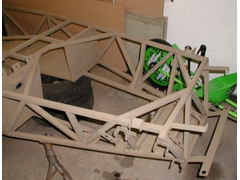
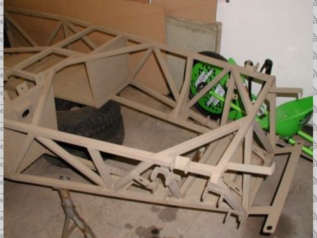
tube rather than 1" square. Yes an X-Brace would improve things but I think it is better to do something like I have done on my own chassis. See
below: (Comments, Good or Bad welcome)
Btw, all the sheet sections you can see here are seam welded 1.6mm steel plate. (ie. Footwells, main floor and under the steering rack area)
Cheers,
Craig.

[Edited on 24/9/2004 by craig1410]
|
|
|
Rob Lane
|
| posted on 24/9/04 at 12:18 PM |
|
|
Craig,
Looks excellent, most of the mods you have are what the Oz guys developed.
Just one other thing, is that standard book steering rack mounts? If so you will need to beef those up slightly as the rack is subject to flex using
the book mounts.
Update: I've just looked at your site and seen the extra strength rack mounts.
[Edited on 24/9/04 by Rob Lane]
|
|
|
Cita
|
| posted on 24/9/04 at 03:55 PM |
|
|
I dont think that Cymtric made a guru of himself,all he did was post a analysis of some modifications he made,no more no less.
It's of course up to the builder to use or not use those modifications.
The only thought i have is that we all seem to except for example our crappy welding (as mine!) but when it comes to modifications all of a sudden the
safety aspect is brought in.
If Mark Allanson would inspect the welding on our cars i'm sure he would scrap at least 50% as unsatisfactory,still we feel it's safe
enough.
|
|
|
Hugh Jarce
|
| posted on 24/9/04 at 09:00 PM |
|
|
That's the way to do it! Carve the chassis in one piece from a laminated block of MDF.
Beautifully done too.
Rescued attachment MDF_chassis.jpg
The pay isn't very good , but the work's hard.
|
|
|
craig1410
|
| posted on 25/9/04 at 03:30 PM |
|
|
Hugh,
It does look like MDF doesn't it! Never thought of that. 
It's a nice gloss black now though.
Rob,
Many thanks for the compliment!
I must admit I am quite pleased at the way it evolved! It all kinda came together at the last moment to be honest as a result of my wish to build an
engine "cradle" into the chassis for my Rover V8 and use the Rover SD1 original engine mounts. Also, given that it is a V8, I can't
use the long "R" tube so I elected for two shorter "R" tubes. This gave me a convenient place to join my two triangulation
tubes on the side so they coincided with where the "R" tubes hit the "J" tubes on the top. The changes to the front assembly
are as per cymtriks suggestions but to be honest I had decided to triangulate the front anyway because it seems like such an obvious weakness.
My steel plated areas are perhaps overkill but I wanted my floor and footwells to be made from steel for safety reasons as much as structural reasons.
I hope that they will stop or at least slow down any fragments of steel tubing which try to come my way in a frontal impact.
Generally speaking I have approached my build by simply trying to ensure that there are as many triangles as possible in my chassis and no large gaps
between chassis tubes and/or long unsupported chassis tubes like TR1 and TR2. I also believe that a welded rollover bar is the way to go because
(IMHO) it is a crucial chassis member for safety and will aid stiffness too.
By the way, a friend of mine is also using a Rover V8 engine in a +4" wider than book chassis and he originally had some problems with flexing
of tubes J1 and J2 when jacking the back of his car up with the engine installed. He could actually see J1 and J2 flexing outwards and had to make
some refinements to stiffen things up. I certainly can't detect any flexing of my chassis when I jack up any of the corners. I have tried
sitting the chassis on four axle stands (with engine and running gear fitted) and then jacking up one corner to JUST lift it off the corresponding
axle stand by maybe 1/16 inch or so. What seems to happen is that the other side lifts off the axle stand by the same amount which I think it a good
sign.
Cheers,
Craig.
|
|
|
Jasper
|
| posted on 25/9/04 at 04:13 PM |
|
|
Interesting reading, this thread. Gonna be building another chassis next year with lots more power and these mods seem like a good idea. Does anybody
have a diagram of the Oz mods?
Craid, your engine bay mods look well worth doing, as do the fully welded steel plate. Are you doing anything to the back end?
|
|
|
craig1410
|
| posted on 25/9/04 at 07:19 PM |
|
|
Hi Jasper,
Rather than post more pics here I will direct you to look at the APR 2004 section of my build diary on my
website as there are a few pictures which show various bits of the backend. To be honest I would do the
back end differently if I did it all again because I had to make some compromises due to my partially home made de-dion design. Also I would make
tubes W1 and W2 out of 1" square section rather than 3/4" as I think this is a potential weakspot.
You will see I have a welded rollbar which is made from 48mm x 3mm wall black pipe. Not the strongest steel in the world but the extra cross sectional
area should make up for the lack of tensile strength and it should be strong enough. I was going to fit diagonals but I needed upper harness mounts
and thus had to fit a horizontal bar instead. I suppose you could triangulate it above this horizontal bar if you wanted to. My turrets above the
dampers have two thicknesses of 3mm plate because your turrets need to be thicker than the rollbar material to avoid punch-through. My rear braces are
partly cosmetic and partly to make up for the lack of strength in W1 and W2 as mentioned above. Fo this reason I don't consider my rollbar to be
"fully sorted" and this is something I would do differently next time. I would probably relocate or do away with W1 and W2 and have proper
rollbar diagonals going to the bottom corners of the rear chassis as per FIA spec.
I had to make a few changes to the seat back chassis tubes due to my unusual "inboard" trailing arms and again there is room for
improvement I think but it should be reasonable.
Let me know if you have any other questions and I'll be happy to provide any help I can. I'm busy modelling my chassis in an FEA program
called GRAPE to see if there are any weaknesses and will report my findings when complete.
Cheers,
Craig.
|
|
|
stressy
|
| posted on 26/9/04 at 08:09 AM |
|
|
Hi Craig,
What laodcases are you using for assessing the strength of your chassis? just being nosey, sorry.
Cheers
Chris
WHO DARES SPINS
|
|
|
craig1410
|
| posted on 26/9/04 at 10:15 AM |
|
|
Stressy,
Please excuse my ignorance of the technical terms surrounding Mech Eng. I'm only a mere Electronic Eng graduate... 
On the assumption that "Loadcases" simply refers to the Load Constraints and Loads (Grape terminology) I am fixing the rear suspension
mounts in all 6 degrees of freedom and then applying equal but opposing forces in the vertical(Z) axis for the front two suspension mounts. I've
not actually completed the whole chassis in Grape yet so watch this space...
If what I have suggested is not the best way to assess chassis stiffness then I'd appreciate any advice you can give me but it seemed the most
obvious way to set it up initially at least. I intend to play with different setups later to assess stuff like offset frontal impact, side impact,
rollover and other relevant scenarios.
Has anyone else tried using Grape (website here) and if so, can you comment on its suitability/accuracy?
Cheers,
Craig.
|
|
|
leto
|
| posted on 26/9/04 at 02:05 PM |
|
|
My 25 öre worth.....
If it ain't broke improve it.
The book chassis works, no question about that. If something was terribly wrong this forum wold show it. We talk improvement here and a good question
to ask before we star talking about what to do is: Why are we doing it?
Increased torsional stiffness is a way to improve handling. The torsional bending of the chassis will do some of the work the springs are supposed to
do, only without any dampers and not as predictable. Higher torsional stiffness will give you better control over the suspension and, if you know how
to exploit this, a faster and safer car.
A locost built by the book, will handle quit good, so it ain't broken. But it's not to hard to find things that can be improved to make it
even a little better.
As for the original question
Chassis Analysis: A Waste of Time? Yes, except if you want your car to be a little faster round the track than the others.
Cheers!
I'm gonna ride around in style
I'm gonna drive everybody wild
'Cause I'll have the only one there is a round. (J. Cash)
|
|
|
leto
|
| posted on 26/9/04 at 02:35 PM |
|
|
Craig
Tried Grape some years back. IIRC it do beam/truss analysis. Shells would be handy to do a fair analysis of a locost chassis, since there are some
stressed skins.
Your chassis look grate! I especially like the bit between the engine mounts and the bulkhead. Might borrow that one.
Cheers!
I'm gonna ride around in style
I'm gonna drive everybody wild
'Cause I'll have the only one there is a round. (J. Cash)
|
|
|
craig1410
|
| posted on 26/9/04 at 03:25 PM |
|
|
Leto,
Firstly, thanks for the compliments. Did I mention I had patented my design? Don't worry, the Royalties aren't that expensive...
Regarding your first posting, while I agree with all that you have said I would like to add to it that there are times where you should definitely
seek to improve the standard chassis and that is when some other aspect of your design has perhaps reduced normal chassis stiffness. In my case using
two shorter "R" tubes to make room for my V8 is likely to reduce chassis stiffness by a significant amount (as per cymtriks notes) so my
extra triangulation is included to restore (and hopefully exceed) the status quo in this regard. Also, the Locost chassis is designed for a lighter
engine than I am running and so I think it is reasonable to attempt to stiffen the chassis to cope with this.
In general, I would suggest that anyone modifying the chassis should consider the other elements of the car, in particular the suspension wishbones,
trailing arms and panhard rod because the chassis changes may result in increased loads on these components. If you were to make the chassis
infinitely rigid then all stresses would be concentrated into the suspension mounts and components which they were probably not designed to handle.
Think of the car as a "system" of interconnected components and make sure you don't move the weak link (there is always a weak link
in any system) to a component which, if it it fails, would produce a catastrophic accident.
Cheers,
Craig.
|
|
|
stressy
|
| posted on 27/9/04 at 11:20 AM |
|
|
more info for craig
hi mate, back again, apologies for any confusion caused by my load case terminology.
Your basically correct with you response tho. when doing FEA you have constraint sets and loadsets (or cases).
Constraint sets may be for example, all four wheels supported to analyse overall bending, or 3 wheels supported one free for one wheel bumping, or
rear wheels free to rotate but not move in space to look at a load applied from the front.
Loadcases correspond to these as maybe maximum braking inertia, lateral inertia, maximum bump etc.
The common approach with playing with chassis is to look at a simple torsional efficiency model, i.e twisting front to rear. This permits a
comparative analysis of stiffness based on twist angle per unit load. On this basis you just need to apply a consistent approach as you are not
always looking for real world values but just a comparison.
The accuracy of the constraints and load method with respect to the real world is the more complex aspect.
The thing to remember is that a comparitive stiffness test is just that, and a such strength must be evaluated seperately for the appopriate loads
which may be encountered, with appropriate factors of safety applied. i think somebody already commented about the relationship between stiffness and
strength?
Its also worth conemplating the stiffness to weight ultimate tradeoff and if your going really light then buckling stability.
I apologise for the vaigness of my post but it would take me days to try and cover everything!
If you ever fancy a chat just u2u and i will try and be as heolpful as i can without treading on anyones toes.
Cheers
Chris
WHO DARES SPINS
|
|
|
craig1410
|
| posted on 27/9/04 at 11:51 AM |
|
|
Chris,
Thanks for that, it's quite an involved subject once you start to look into it...
Yes, I am aware that comparisons to real-world figures are not within my capability but my aim is firstly to "test" the book chassis and
then see what happens when I widen the chassis 4" with everything else staying the same. Then I'll change the front end to match my own
chassis and see where that leaves me. I also want to see which members are highly stressed in various scenarios to see if additional gussets or
chassis tubes are necessary.
The chances are, given that I've now painted my chassis, unless I find a major deficiency this exercise is just an effort to better understand
structural design and no changes will result from it.
Cheers,
Craig.
|
|
|
stressy
|
| posted on 27/9/04 at 12:07 PM |
|
|
Have fun
WHO DARES SPINS
|
|
|
leto
|
| posted on 1/10/04 at 07:35 AM |
|
|
quote:
Originally posted by craig1410
Leto,
Firstly, thanks for the compliments. Did I mention I had patented my design? Don't worry, the Royalties aren't that expensive...
Cheers,
Craig.
Royalty offer:
------------------------------------------------------
I.O.U. (Craig) 1 (one) beer of choice.
To be delivered without unnecessary delay when we meet.
Leto
------------------------------------------------------
OK?
If you press me I might double that offer
Cheers!
I'm gonna ride around in style
I'm gonna drive everybody wild
'Cause I'll have the only one there is a round. (J. Cash)
|
|
|
Spyderman
|
| posted on 1/10/04 at 05:42 PM |
|
|
Just an observation that may be wrong!
It seems to me that there is some confusion or mistaking with the intentions of the chassis modifications.
Without applying any physical analysis by myself to the mods being discussed, just using what knowledge I have gained, it seems that people are
mistaking modifications intended on improving chassis torsional stiffness with safety issues.
There are as far as I know of no chassis safety tests that have been conducted. All tests so far seem to be FEA torsional tests (although I may be
wrong).
Making a chassis stiffer torsionally does not nessesarily make it safer, especially if material is removed to counter the extra X bracing.
It seems to me (again surmising) that the Aussie mods are the most beneficial, but without further testing it is all theoretical.
The only mods I see that could actually be called safety mods would be the addition of a full roll cage.
With an open top, open wheeled car there is very little that can be done to improve safety. Going full bodied open top can make as big a difference
from a seven style car as going to fully enclosed body (tin top) from a full body car.
It is all a compromise!
So if you want it stiffer then you have nothing to loose in trying the mods, but remember that every component removed could be a safety issue.
Just my opinion!
Terry
Spyderman
|
|
|
stressy
|
| posted on 1/10/04 at 08:03 PM |
|
|
Spiderman
Have alook at my post about 5 or so above this one, you will see my attempts to suggest that an indicative torsional stiffness analysis finite element
approaches is mearly a stiffness comparative tool and that strength assesemnt must be dealt with elsewhere using appropriate loading and constraint
conditions.
When i ran ana analysis in about 1998 i ran 6 load cases, 2 stiffness and 4 strength. static strength cases were defined based upon dynamic loading
equivelence. for the front impact case a non linear approach was applied in order to better characterise the structures ultimate behaviuor and
identify any potentailly failure modes.
FEA will always give you the correct answer to many decimal places, engineering is about asking it the right questions......
WHO DARES SPINS
|
|
|
cymtriks
|
| posted on 14/10/04 at 09:10 PM |
|
|
constraints - craig1410
Craig,
constraining all six degrees of freedom on both rear mounts is technically a no no as this removes any strain in the lateral chassis tubes. This is
probably a small thing, but still wrong.
I'd suggest the following:-
Rear suspension mounts constrained vertically, a rear mid point constrained laterally and axially, a front mid point constrained laterally and
vertically and the front suspension loaded one side up and the other side down.
This permits the chassis to adopt its natural shape under tosional load without adding extra stiffness.
|
|
|
craig1410
|
| posted on 14/10/04 at 10:28 PM |
|
|
Cymtriks,
Yes I see what you are getting at and it makes sense. To be honest I've not made any progress with my FEA activities in the last couple of weeks
but I'll hopefully find time in the next week or so to revisit it. I'll certainly adjust my constraints as you suggest.
Thanks,
Craig.
|
|
|
pgpsmith
|
| posted on 16/10/04 at 01:37 AM |
|
|
Stressy,
In an earlier post you mentioned making some safety mods. Are they something you can share with us?
This has been a very informative thread. "Thank you" to all who have contributed.
Regards,
Mr. (still in CAD) Pete
Live and don't learn, that's us. - Calvin and Hobbes
|
|
|