

Chassis mods
[Edited on 20-12-07 by speedyxjs]

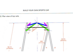
I have struck a problem. Due to the size of my engine, tubes T and S (in original book) dont quite fit. They will fit if i make them 3/4 of the length but that may be defeating the point of them. Any suggestions?
don't you own a camera?
quote:
Originally posted by Mr Whippy
don't you own a camera?

This should make more sense. The tubes (green) will only fit if i move them to where the blue ones are. Does this matter?
This might help 


Chassis mods
[Edited on 20-12-07 by speedyxjs]
Looking at the book the tube length looks to be quite critical.
How much were you looking to be shorten them by ?
I have just noticed by about 25%. A tad too much I think.
They look like they provide critical triagulation for the upper wishbone assemblys, tr1 & tr2, fu1 &fu2.
I am sure you will get some more advice on this.
Ronnie

can't you do a curved piece instead, you've not left every much, a bit drastic
can you mark out where the engine will sit? i think i can see some more triangulation possiblities, but don't want to draw them out if
there's a good reason why it won't work  i'm lazy like that
this is what MK did, it has left a lot more room
[Edited on 20/12/07 by Mr Whippy]
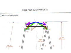
Ok.
Green line = original design
Blue line = obviously wont work
Pink line = Another idea (waiting for abuse
Black line = Where engine comes to (approx)
Edit - Liking you idea Mr W 
[Edited on 20-12-07 by speedyxjs]
To what plans are you using ?
The book plans or the +4?
pink is nuts
quote:
Originally posted by Mr Whippy
pink is nuts

 )
)
bent tubes are bad. bent square section where one wall is buckled in seems even worse.
if i were to need the extra space, i'd go for something like below. it'd be harder to weld, but i'd imagine you could get into it all
if you were a bit creative with mig shrouds
tom
Rescued attachment untitled2.JPG
^^^^^^ Thats a good idea^^^^^^
i would go with something like this (red), and maybe continue them forward past the blue ones like the pink ones


tubes
[Edited on 20/12/07 by blakep82]
quote:
Originally posted by speedyxjs
^^^^^^ Thats a good idea^^^^^^

Just thinking that the +4 is a tad wider where it matters most with the standard chassis width at the point shown being 506mm for standard chassis and
608mm for the +4 chassis
Would the extra 102mm help in resolving the initail problem in the first instance with clearance
Can someone tell me if the Haynes chassis is 506 or 608 at the front end on the top
[Edited on 20/12/07 by Blakey_boy]
[Edited on 20/12/07 by Blakey_boy]
oh off coarse it's the jag engine...what were you thinking, fitting that ??
[Edited on 20/12/07 by Mr Whippy]
quote:
Originally posted by Blakey_boy
Can someone tell me if the Haynes chassis is 506 or 608 at the front end on the top

quote:
Originally posted by Mr Whippy
oh off coarse it's the jag engine...what were you thinking, fitting that ??
[Edited on 20/12/07 by Mr Whippy]

so are you building a +4 locost or a +4 haynes roadster?
a haynes roadster is 2" wider than a locost, so a +4 roadster's a +6 locost
did you follow that? you can have a merit if you did.
tom
thats 150mm longer and 150mm wider!!!
That would make the chassis at the front (if the haynes chassis is 608mm wide at the front) 760mm (app) which is nigh on 30 inches wide!!!
And that is between J1 & J2 810mm or 32 inches if you include J1&2 overall
[Edited on 20/12/07 by Blakey_boy]
quote:
Originally posted by indykid
so are you building a +4 locost or a +4 haynes roadster?
a haynes roadster is 2" wider than a locost, so a +4 roadster's a +6 locost
did you follow that? you can have a merit if you did.
tom

760mm (app) overal width or for those following this thread 30 inches (app)
A PLUS 8 LOCOST???
didn't luego get a jag straight 6 in a viento?
that's only +442 afaik.
is it technically acceptable to just scale up the locost chassis? are you still using inch square tube?
tom
quote:
Originally posted by indykid
A PLUS 8 LOCOST???
didn't luego get a jag straight 6 in a viento?
that's only +442 afaik.
is it technically acceptable to just scale up the locost chassis? are you still using inch square tube?
tom
I have been giving your dilema a bit more thought.
Looking at the black line of where you engine will be coming to. I am not sure if yor engine uses the full width at the line, probably not.
One possible solution may be as follows:
Take some 1.6mm sheet metal. Cut 4 pieces of curved sheet ( Boomerang shape )
Try to keep as near as you can to the original tube length.
Weld two on each corner. One level with the top of the box section & one level with the botom.
Close the two plates with a pice of strip steel.
This will completely close each corner in.
This should give you some very rigid corners.
I hope this makes some sense to you.
Its the best solution that I can come up with.
Ronnie 
Morning bonzoronnie.
My brain isnt working this early in the morning. Can you provide a visual aid?
quote:
Originally posted by indykid
bent tubes are bad. bent square section where one wall is buckled in seems even worse.
if i were to need the extra space, i'd go for something like below. it'd be harder to weld, but i'd imagine you could get into it all if you were a bit creative with mig shrouds
tom
quote:
Originally posted by indykid
A PLUS 8 LOCOST???
didn't luego get a jag straight 6 in a viento?
that's only +442 afaik.
tom

The wheels look bigger too
quote:
Originally posted by speedyxjs
The wheels look bigger too


I nicked this earlier image & done a quick paint 


The red shaded area could be shaped to fit around your engine & fully boxed in.
If the lengths are kept as close as possible to the book spec lengths. A good amont of the original strength should be kept.
Ronnie 
[Edited on 21/12/07 by bonzoronnie]
quote:
Originally posted by wilkingj
quote:
Originally posted by indykid
didn't luego get a jag straight 6 in a viento?
that's only +442 afaik.
tom
Viento is +6" wider, +12" longer, +4" taller than book chassis.
Its a BIG bugger.
[Edited on 21/12/2007 by wilkingj]
Speedy besides the problem of the front tubes hows the rear end coming?.