MotaLeira, today's progress
nitram38 - 3/7/07 at 11:05 AM
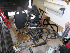
Some more photos of the layout of the chassis. I have just started spacing the front/rear subframe and seat frame from the floor and checking the ride
height.
Next I will be bending some conduit to form the curved joining side rails, which will join the whole lot together.
These will be used as a pattern for a company to roll me some from 1 1/2" round 16 gauge.
In one of the photos of the hub, you can see the camber already (the photo exagerates it a bit). The front wishbones will rise up towards the wheel.
Obviously the rod ends need setting, but you get the idea!
I had to stop as it started to rain. I need to get outside to bend the conduit!


Description
[img][/img]
[img][/img]
[img][/img]
[Edited on 3/7/2007 by nitram38]
ned - 3/7/07 at 11:14 AM
Looking good, is the x-brace above the dif carrier going to be bolted on for access to the running gear/engine?
and is it the angle of the pic or are the driveshafts going to be angled slightly towards the rear of the car?
[Edited on 3/7/07 by ned]
nitram38 - 3/7/07 at 12:33 PM
Ned, the X-brace will be removeable. It holds the top rear engine mount and the top of the diff carrier/tensioner.
I am waiting for some bushes to be made that take recessed cap screws and some threaded bobbins for the subframe.
There will also be another removeable frame on the rear of the subframe and some more triangulation along the sides.
I am also waiting for a bush that spaces my reverse starter motor, before I can weld anymore traingulation.
The engineers around here are very slow!
Driveshafts are straight, it is probably the wishbones that draw your eye. They will also run parallel to the ground.
[Edited on 3/7/2007 by nitram38]
Mave - 3/7/07 at 08:26 PM
Looks very good. Keep us updated!
Must be nice to build something that you prepared into detail before starting the actual build.


