
McSorley 442 accuracy
9000rpm - 22/6/07 at 09:11 PM
I am teaching myself solidworks and decided to build (on solidworks) the chassis of the +442.
I started off by building the bottom rail individual pieces and finally started the assembly mating the pieces together.
Apart from minor discrepancies within ~1mm, the F1 and F2 are off big time.
For E.g. according to the PDF page10 the F's are apart 155mm from the front. On my assembly they are a drastic 181.7mm
http://i131.photobucket.com/albums/p298/Trip_gtir/assem1.jpg
Now it’s either me or the pdf is wrong although I checked my work over and over. 
Comments please.
Thanks
Mansfield - 22/6/07 at 09:18 PM
I think E is too far forward.
9000rpm - 22/6/07 at 09:21 PM
quote:
Originally posted by Mansfield
I think E is too far forward.
E is off cause F1 and F2 are. If E was backwards, it would sit without touching the F's.
I just put E to touch both F1 and F2 at either side.
omega 24 v6 - 22/6/07 at 09:41 PM
Vheck your sizes again as not all of the tubes are measured from the same datum. From memory, one of the sizes is to the rear of a tube, and the next
size is from the front of a tube, leaving a 25mm discrepancy. I'm sure I had the same bother drawing it in autocad BUT it does all fit together.
ecosse - 22/6/07 at 09:48 PM
As stated you have got "e" too far forward (edit: I'll get it right yet!), which is causing F1 and F2 to be splayed out wider than they
should be.
Cheers
Alex
"BUT it does all fit together" sure does 
[Edited on 22/6/07 by ecosse]
[Edited on 22/6/07 by ecosse]
[Edited on 22/6/07 by ecosse]
Mansfield - 22/6/07 at 09:51 PM
The drawing is full of rounding errors, also the inch to mm conversion is slightly off.
You would be better off starting again without using the angle dimensions and the lengths of C and E. The angles and C & E lengths will generate
themselves.
I drew mine in inches and scaled up (x25.4) so I got less missing fractions.
9000rpm - 22/6/07 at 09:54 PM
quote:
Originally posted by Mansfield
You would be better off starting again without using the angle dimensions and the lengths of C and E. The angles and C & E lengths will generate
themselves.
Good Point. So I lay the dimensions and let the angles come along ?
Mansfield - 22/6/07 at 09:58 PM
Can you read AutoCAD drawings?
9000rpm - 22/6/07 at 09:59 PM
quote:
Originally posted by Mansfield
Can you read AutoCAD drawings?
I think I can
Mansfield - 22/6/07 at 10:07 PM
No need I have posted a screen dump.
I used all the lengths given along the length of the car, the max width of the car, the 25" length and the 6.1" width between the F1 and F2,
the rest will generate when you add the box widths.
C and E are not exactly as McSorley but 34.4 x 25.4 does not equal 875 anyway.
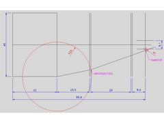
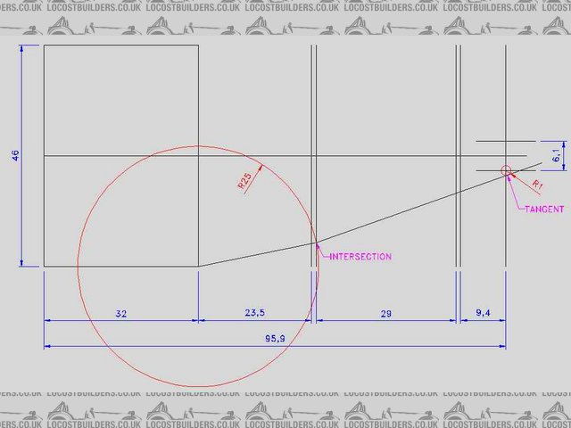
Rescued attachment ImageA.jpg
9000rpm - 22/6/07 at 10:14 PM
Ok I understood. Thanks for the image.
I will contruct it using the base dimensions and the rest will fall into place accordingly.
I am working on another image showing the same dimensions as swown on Page10 on PDF but with different measurements.
Mansfield - 22/6/07 at 10:17 PM
Watch out for the front suspension pick ups, they definately are wrong.
Check out omega 24 v6's photo archive and you will see.
9000rpm - 22/6/07 at 10:25 PM
quote:
Originally posted by Mansfield
Watch out for the front suspension pick ups, they definately are wrong.
Check out omega 24 v6's photo archive and you will see.
THANKS.
omega 24 v6 - 23/6/07 at 01:23 PM
quote:
TextWatch out for the front suspension pick ups, they definately are wrong.
Yip it's the only problem area that I've come across so far and after today my chassi frame should be complete barring a few brackets. If I
was doing it again I'd adapt and build a book chassis + 2 inch in height.
