Is this a regular problem or is there something about the design of the quick rack that is causing problems, if so what should I do to get this sorted?
Help!
Caber


I have an escort quick rack from Raldes and the spline is more or less centered on the back wall of the FU tube. I have dropped the rack and moved it
forward from the book position to try and get the steering arms at the correct angle to the Cortina uprights. At any event the steering arm joints
will not align with the wishbone chassis mounts so there looks to be a lot of bump steer.
Is this a regular problem or is there something about the design of the quick rack that is causing problems, if so what should I do to get this
sorted?
Help!
Caber


Mine is very close, had to put in a rose joint to make sure it didn't touch, pictures in my www, they may help.
Regards
Rich
Nice solution with the rosejoint Rich 
I'm having similar probs as you Caber, although I can just squeeze the steering rod past the chassis, but this leaves me with a bad angle to
connect to the column But I think Rich has just solved that for me

One other possibliity I am looking at is raising the rack higher so it gets the benefit of the extra width at the top of the chassis uprights (does
that make sense?) although this leaves the steering links arms pointing down (steep angle) to connect to the uprights, but if you use rosejoint ends
and drill the steering arm on the upright so that you can mount the steering arms to the top of the uprights, rather than the bottom, it levels out
quite nicely, it also (not confirmed yet) should help with the bump steer problem, as the rack ends are nearly in line with the top/bottom wishbone
pivot points 
Has anyone else done this, or am I way out on a limb here?
I can probably post pics it would help and if my ramblings above dont make sense 
Cheers
Alex
Alex I think I understand but pics would help!
Would it work if you swap the uprights left to right and inverted them thereby moving the steering arms to the top?
Caber
I'll do some pics directly (just in from work)
I thought about reversing them but that would mean the top and bottom BJ would be upside down as well...I think ..thinking about that has given me a
sore head
Pics shortly
Alex
Thinking about that some more, the bJ's would be the right way up but it would through the camber out as the top BJ is set further in than the
bottom, am I right?
[Edited on 2/10/06 by ecosse]
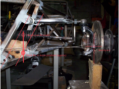
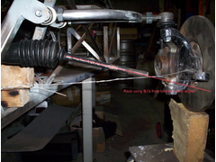
Sorry about the lash up (had to throw it together for the pics!) hopefully it shows what I mean about the rack being located higher and how that would
affect bump and angle of steering arm
With a pic this time hopefully


[Edited on 2/10/06 by ecosse]
And again?


Rescued attachment rackposition1.jpg
Rack high but showing angle required for BJ to upright steering arm


Rescued attachment rackposition2.jpg
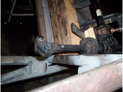
Last one, showing the gap between the column link and the chassis vertical.
If I sit the rack in amore traditional position it hits the chassis, so its either shorten the rack so it all fits with (presumably) no bump steer, or
leave it standard, raise it and use rose joints down through the top of the upright steering arm


Rescued attachment column gap.jpg
Note that simply having the inner track rod ball joint in like with the upper and lower wishbone bushes does not guarantee you will not suffer from
bump steer. This is fairly obvious if you think about it because the wishbones are not parallel and the angle between them changes as the suspension
compresses, essentialy moving the upright closer or further away from the rack.
The location of the rack fore and aft also makes a big difference.
Another thing, in normal use, the top wishbone isn't horizontal, it's angled up 10 - 15°. This will bring the balljoint closer to the ideal position.
Have you got the top part of the column in place? That steering link is pointing towards the outside of the car, your column top will be further in, that's why the bottom joint is flexible so you can aim it where it needs to go.
Mikerj
Yes aware of that, but it has to be closer to the optimum than a rack in the standard position with the rack ends well outside the line of the bone
bush points?
Or am I missing something here (quite possible
 )
)
I was unaware that the top bone would be angled up (when the bottom one is level?), I thought that was just the result of using sierra uprights?
So as Marcus says, that would straighten it out even more.
Pete: yeh column in place and the link will bend into line, I wasn't sure how good an idea that was though, would a UJ be a better option or will
the rubber joint work okay while pulled out of line?
Is that all workable for you Caber, if you mounted the rack high as shown does it give you the clearance required for the steering rod?
Cheers
Alex
My calculations and geometrical studies put the steering rack a little further back towards the axle c/l than in line with the upright balljoint
position.
Might help if you move the rack back a little?
Cheers,
Syd. 
This is a common problem. I think the problem lies in the misunderstanding of the position of the FU tubes in the book.
I believe you have positioned them as the drawing shows in the book. What we do is to move the lower part of the FU tube much further outboard onto
the next peice of tube, at the same time we tip the top of the FU tube further inboard, but, such that it still pickups up the top rear wishbone
bracket in the same place, just at a different angle.
In practice the best thing to do is to jig the top rearward wishbone bracket off the other three so that it hangs in the right place in 3D space. Then
run the FU tube up the back of this bracket such that the bottom of it hits the chassis rails as far outboard as possible. You'll notice the top
tips in alot, but because the triangulation tubes from the top rails are above it you have plenty of tube to get onto and weld too.
Bit wordy, but, hopefully that'll help. You;ll find you have plenty of rack clearance this way. I think we may have bought the steering column
over by 5mm to help as well.
Kind regards,
Darren
Thanks for the input folks. I set my FU tubes from a jig made to hold the upper and lower wishbones in the correct realtive positions with the
uprights on. At that stage i had the rack in the book position and everything cleared. Once I had wishbone brackets on I then added Cymtrics
triangulation that helps to brace the upper brackets, put it all together and found the steering arms were pointing down. I then read the collective
wwisdom of the list that said you should move the rack down to flatten the steering arms that was when i found out that the joint fouled the Cymtricks
triangulation so I cut that out and then discovered that the line still fouled the bottom of the FU tube though this is set to the outside of the
chassis bottom bars! At this stage I had given up hope of finding a position that met the bump steer criteria as for this rack it would have to be
mounted near the top of the chassis! As I understand the geometry the bump ster will still happen on bends as the knucles on the steering arms are
naturally out of line with the wishbone pivot points.
I think I need a new bottom link as I cut mine to make the extension, it looks like a standard one would pass the FU tube and I would re direct from
the next joint upwards though i will have to put the engine back in to check the line clears the exhaust manifold and alternator
There i was thinking I was on the home run!
CAber