
Removing tubes G1/2 for a BEC chassis?
Gav - 18/2/06 at 08:04 PM
Since these G1/2 are used to mount the plates for a car engine mounts, i am thinking of removing these to allow better clearance for my blade engines
oil filter as it is almost touching, i would then put corner braces in place instead.
Any thoughts on this?
DIY Si - 18/2/06 at 08:32 PM
Can't see a prob myself, as long as the support is put back in somehow. Such as the corner braces. Not sure if it affects the strength of the
chassis in a front-to-back direction at all though.
cymtriks - 18/2/06 at 08:38 PM
Those G1 and G2 tubes do more than just support the engine. They are the only triangulation on the bottom of the engine bay. As the TR1/2 tubes are
only really adequate for lighter engines and the R tube is the bare minimum needed for the top then you really are cutting it fine to remove the
bottom triangulation.
Why not post up a picture of your corner diagonals? How you intend to arrange these will determine how good an idea this is!
mark chandler - 18/2/06 at 08:42 PM
I followed the advise of Jon Ison and have installed my blade engine back as far as possible and following the bonnet line, not the centre line of the
car.
This give a decent drivers footwell and the prop is nearly straight down the centre of the car.
I cut G1 halfway down and braced around the sump. The edge of the sump now sits just infront of ‘C’ with the waterpump crossing this. The passenger
footwell now starts at ‘P’.
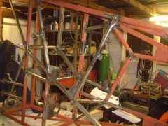

Rescued attachment Engine bay detail.JPG
mark chandler - 18/2/06 at 08:49 PM
Here's one with the lump in !
Note that I have extended 'R' back to 'P', it is also more diagonal within the car and the engine mounts also brace the engine
bay
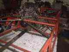

Rescued attachment engine in.JPG
mark chandler - 18/2/06 at 08:52 PM
Bit of a poor picture
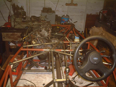

Rescued attachment Centre chassis 12 feb 2006.JPG
Gav - 18/2/06 at 10:55 PM
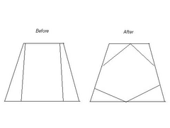
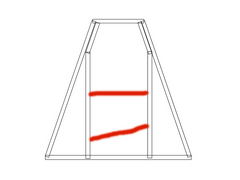
OK here is an extremly poor, beer fueled diagram of what i mean.
I would have to measure tomorrow to show the exact position of the tubes, but they are meant to be pretty equal although
id expect the bottom left tube would not be quite as equal as the right hand side as this is where my problem lies with clearance.
The front two tubes could all the way back to almost halfway of the bottom off this section i think.

Description
[Edited on 18/2/06 by Gav]
Jon Ison - 19/2/06 at 05:25 AM
I think after will be better/stronger/more ridgid than before. I could think wrong though.
mark chandler - 19/2/06 at 10:33 AM
Better if all the pipe ends join, it does not have to be symetrical so you should be able to achieve this on the off side at a minimum.
Drop the engine where you want it and build around, Just make bigger triangles !
The lower front wishbones are braced by G1 & G2 so you will want to beef it up at the front corners.
Peteff - 19/2/06 at 01:18 PM
I've done mine like I did my first car and added a couple of stays in the base to mount the lower brackets on the engine.

Rescued attachment enginebay.jpg
C10CoryM - 19/2/06 at 05:19 PM
Well, personally I dont like the before or the after  .
.
The locost is supposed to be a space frame/backbone chassis. I would call it a 4 bar/backbone chassis because to be a space frame it must be properly
triangulated. In all fairness, engine bays and cockpits are always hard to triangulate correctly and the locost was not intended to be perfect.
For example the book chassis tubes G1/2 join C in the middle. This introduces a beaming force into C. G1/2 "should" go to the corner of
C/M and C/I. That rids the beaming load in C but still doesnt triangulate the engine bay. Triangulate means triangles. Anytime you see something
other than a triangle its not good.
For the after drawing, your new tubes must join on tube F and have a 3rd tube going across from that junction. Otherwise you will put
beaming/twisting forces into F. You usually have to get creative to get around the oil pan. What you should do is make a drawing of where your
oilpan and anything else that hangs down in between the lower rails are. Then maybe we can give you some idea on how to clear it and keep the engine
bay stiff(ish  ).
).
Cheers.
PS: Not hacking on anyones locost or design ideas. If your car does what you want it to do, thats all that matters.
Jon Ison - 19/2/06 at 05:28 PM
All fair points, but the one "big" plus fitting a bike engine into a locost chassis is you can close up the bottom of the transmission
tunnel where it meets the engine bay, this adds loads of stiffness and rigidity too the chassis.
Liam - 19/2/06 at 06:30 PM
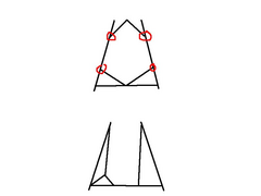
The 'after' is definately not a good idea! Especially if the top of the engine bay is like that too. The front and back parts are stiff,
which only makes it worse for th etotally untriangulated middle section that is free to parallelogram all over the place. The stress on the joins
ringed on my diagram would be horrendous!
Cymtriks analysis will tell you that removing the top R tubes and replacing them with two short tubes to the middle of the outer tubes is bad enough
for strength/stiffness. Doing it to the bottom of the engine bay too would be dangerous imho unless the outer tubes were all significantly
uprated.
Much better would be something like my bottom diagram. You shouldn't need to remove both G tubes for the blade oil filter, and more clearance
could be obtained on one side with a y-brace as shown.
Liam

Rescued attachment enginebay.JPG
Gav - 19/2/06 at 07:34 PM
Interesting! thanks for the input.
This mod is only a nice to have. right now i can place the engine in ok, its just id like a little more clearance on that side for the pipe work and
to put a little more distance between the tube and the oil filter.
After taking all that in, i think the best solution would be to go with Liam's idea of a Y brace.
Liam - 19/2/06 at 07:51 PM
I know what you mean about the blade oil filter if it's the same position as a cbr1000 one. My mate (jambojeef)'s cbr1000 filter is
practically on the tube.
Thank Cymtriks for his FEA work on the locost chassis which led to the suggestion of the y-brace. His document on chassis stiffness is worth
reading...
Liam


 .
.