
A whole day to produce a single lower wishbone... aaargh
mark chandler - 23/10/05 at 06:18 PM
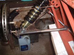
Spent a whole day on this, pleased with the result though.
Got the shock mounting within a inch of the ball joint, V centre is the ball joint and a reasonable gusset (welded in the centre line of the 19mm
tubes), recycled from a Range rover drag link so nice and thick quality tube.
What do you think...

Rescued attachment NSF lower wishbone 23 OCT 2005.JPG
big_wasa - 23/10/05 at 06:29 PM
im making my own chassis but bottled it on the bones..
borght mine today instead 
JoelP - 23/10/05 at 06:54 PM
looks good throughout. Which part is the range rover part? the ball joint? How does it attach? What wall thickness are the main tubes? 'scuse all
the questions, im just curious
Mark Allanson - 23/10/05 at 07:49 PM
I think the upper wishbone is a little on the thin side, it may fail prematurely
Donners90 - 23/10/05 at 08:45 PM
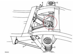
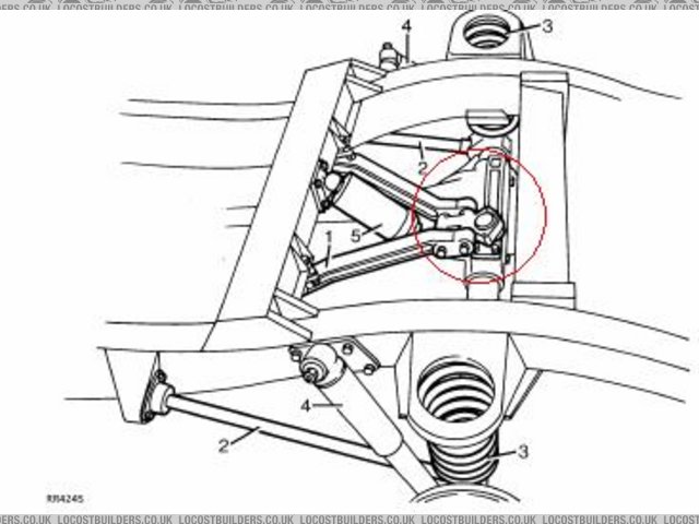
I think the part from RangeRover is highlighted below. Two bolts either side of the ball joint.
[Edited on 23-10-2005 by Donners90]
Rescued attachment untitled.JPG
mark chandler - 23/10/05 at 09:27 PM
Sorry for the confusion.
The ball joint is from a maxi.
On a classic range rover you get two rods for the on the front axle, a short one from the steering box across to the far end steering knuckle. Another
which is behind the axle which ties the steering across the car. The tube I used is this. Its around 19- 20mm od, 3-4mm thick when cut looks like CDS
as no internal weld seam (its harder to bend than the 25mm tube used in the chassis sticking it in a vice and pulling).
Each tube is threaded, both LH & RH so you can twist the tube to adjust toe in and centralise the steering on the box. The TRE's are a
perfect fit for the top cortina upright so this provides the threaded tube for the top bone (next week). On a P38 range rover the same setup exists
with larger diameter tube (these TRE's do not fit) but you do get an inline adjuster with a course and fine thread, I will be using this to
provide toe adjustment for the rear IRS next month.
Having reviewed other designs and posts the book way is not best practice as by placing the shock back from the ball joint when static the load on the
rods is already 1/6 of the cars weight, although you do get more suspension travel, when braking these forces grow along with the twisting effect
across the upright.
On the basis that the shock and diagonals are all pointed at the centre of the lower ball joint the stresses on the rods are minimised, when braking
the bones will be twisted vertically as before but will no-longer supporting the weight of the car at any point. Only The shock absorber is under
compression, the lower bone is under torsion across its entire length.
The axle travel like this measures 6" so I set it half way with the bone horizontal.
Regards Mark

mark chandler - 23/10/05 at 09:32 PM
Just read the first qusetion again so I will bore you some more.
I mounted the ball joint buy getting an 1" of tube that the fat end was a snug fit in. Welder a couple of small tubes either side for the bolts
and capped it with some 2mm plate. Welded this to the ends of the bones, I,ll take a picture tomorrow.
Regards Mark

