Front bones worries- not the same as the usuall
Dale - 16/6/05 at 12:34 PM
I had a couple of people take consern with my front suspension- And for safetys sake I will take the comments seriously.
First off I know of the conserns with the orginal lower arm being stress risers from the shocker plate and bending under extreme loads.
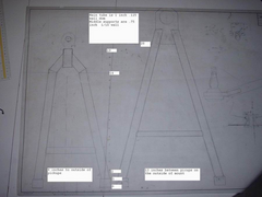
I have attatched a drawing of my arms which are quite longer than the usuall being my car has a very narrow front end (going for a very vintage
look).
I used the book spacing of the bushings fore to aft 8 inches top and 13 bottom i think.
The arms are made of 1 inch .125 wall dom tube with the cross member of .75 inch .0625 wall.
The shock load is completely on the ball joint plate at the end of the arm
From what I read before I thought that most of the loading is done on the lower arm in breaking and say hitting a pothole at the same time.
I do not have any plating between the arm tubes and that could be added to increase the strength if needed.
Secondly I used a spreadsheet I got from somewhere- here maybe- I actually only used the first portion of it to setup the arm location for my car-
being i wanted the pickup points to be completely internal to the bodywork the mounts are quite close together which is why the arms are long. I set
up the points with this spreadsheet but to get a roll center height near where I thought it should be 80mm and get some camber change- .5 deg per 1
deg of body roll the upper arm has alot of angle to it I will attatch a pic as well. My lower arm has a slight incline 1.25 inch ( I know it
should be level) but it should drop .5 inch as I go to the size tire I want on the front. I will attatch the pickup points to here and hopefully
someone could put them into what ever program your using to check your front end. Or point me in the right direction.
Comments good bad or indifferent appreciated.
Thanks Dale
[Edited on 16/6/05 by Dale]


Rescued attachment Resize of Resize of front arms1.jpg
Dale - 16/6/05 at 12:38 PM
here is the clip from excel with the chassis points on it.
Dale - 16/6/05 at 12:45 PM
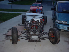
here is the front on view of the mounted arms- the lower arm should drop about .5 inches when the right size tire is installed.
Dale


Rescued attachment Resize of front end.jpg
MikeRJ - 16/6/05 at 01:43 PM
I'd say that design was better than the book one simply because the ball joint mounting plate is very short and narrow, giving a smaller stress
raiser due to change in cross section, and the suspension loads are taken very close to the ball joint giving a very low bending moment.
The only thing I would want to work out is the likely compressive loads on the tubes. By making the wishbones longer, but keeping the mounting points
at book dimensions you are essentialy increasing the compressive (and tensile) loading of the tubes. As long as these tubes have an appropriate
diameter to resist buckling you should be fine.
Dale - 16/6/05 at 01:47 PM
quate of
The only thing I would want to work out is the likely compressive loads on the tubes. By making the wishbones longer, but keeping the mounting points
at book dimensions you are essentialy increasing the compressive (and tensile) loading of the tubes. As long as these tubes have an appropriate
diameter to resist buckling you should be fine
thats the issue I am concerned about.
Dale
britishtrident - 16/6/05 at 03:45 PM
The lower wishbones will have close to zero bending moment which is good. I personally wouldn't use the mitred dog leg in the upper wishbones
but I suspect you will have other handling related problems including a very large dollop of bump steer
[Edited on 16/6/05 by britishtrident]
Dale - 16/6/05 at 03:56 PM
Actually the bump steer is sorted out and is pretty minimal-
Are most of the forces involved in impacting a curb /hole ect on the lower, upper or both arms?
Dale
pbura - 16/6/05 at 05:57 PM
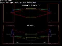
From the photo, your swing axle length looks very short, so I plunked your figures into the Wishbone program. As you can see, you will get a lot of
camber change in bump (2.4 degrees in 2" of bump). The diagram is based on zero static camber:


Rescued attachment front.gif
Dale - 16/6/05 at 06:44 PM
Thanks for running that for me--I have heard of the wishbone program before but am not sure were to find it. I may have been missunderstanding
part of the theory - where do we want camber change to be at-I know I dont want too much but I thought you needed to get some to help counteract
body roll. I had set it -I thought to = 1/2 deg per deg of body roll.
Dale
pbura - 16/6/05 at 07:09 PM
Good program, free at download section of Race Tech Magazine website:
http://www.racetechmag.com/
Well, the good news is that your very low amount of camber change in roll allows you to set up with a smaller amount of negative camber, say 0.3 to
0.5 degrees. The book Locost gains about .8 degrees per inch of bump, and you're at 1.2, so your camber winds up in about the same place (in a
2" bump) as a Locost with -1 degree static camber. Really not worth messing with at this point, IMO.
The wishbones look nice and strong, BTW.


Pete
Dale - 16/6/05 at 08:51 PM
Well thats good news on the geometry - thanks.
I think my bottom arm should be strong enough but have had my doubts on the top one- but I dont know how much stess is put on the top one.
Being that my wishbones are long I have toyed with the idea of covering them to form a airfoil to add a bit of down force, it could structural as
well to add some strengh to the arm as well?
Dale
niceperson709 - 17/6/05 at 05:48 AM
hi Dale
looking good mate and by the way are you a fan of "Mythbusters" as i have heard your aphorism on that show
Best wishes
Iain
Dale - 17/6/05 at 04:05 PM
Its a great show - The wife and I watch it when we get a chance -- but that is where I picked up the line.
Dale
niceperson709 - 17/6/05 at 10:58 PM
Hi Dale
"Its a great show - The wife and I watch it when we get a chance -- but that is where I picked up the line. "
as a downunder fan of the show I could not miss the line it is so apt in the world of "locost" building Keep up the good work mate


