
Review this Chassis Design?
Clay - 20/5/05 at 05:03 AM
This is a chassis ive been working out on paper, i have more refined drawings, but this is the one i keep altering so its kind of messy. Its similar
to a gt40 configuration, v8 with an audi 5000 tranny in the back, double wishbone independant suspension in the front and the back. Its a 2 seater.
This chassis will be made to the length/width/height measurements to fit underneath an existing body.
The main thing im wondering about is structural rigidity vs. weight.
I have used several X-Braces but lots of chassis designs i see use a single diagonal brace inside squares. Am I just adding dead weight by using
X's instead of a single diagonal braces? or is this additional bracing actually adding structural rigidity?
I want to make the most rigid chassis possible with the least weight added.
The chassis has a squared/triangulated center backbone to add rigidity and provide a place to pass the radiator lines through, this used several X
braces, im really trying to eliminate twisting in the chassis.
I understand this drawing is very crude, but offer any insight you've got.
thanks
*edit*
In newer drawings ive moved the steering wheel position so that the drivers arm is slightly bent, but that detail isnt critical in this drawing, the
chassis rigidity/design is what im interested in.


[Edited on 20/5/05 by Clay]
silex - 20/5/05 at 05:05 AM
It says bandwidth exeeded - there is no pic ?
Clay - 20/5/05 at 05:12 AM
I think I fixed it.
[Edited on 20/5/05 by Clay]
silex - 20/5/05 at 05:24 AM
thats better - can see it now
Fred W B - 20/5/05 at 05:53 AM
HI
Your concept is similar to my CANAMSA project, search under that name on here for some discussuion and see my archive
Also go back in the Midengined section posts for a lot of info from various other builders.
One thought, I think you will be short of driver and passenger feet/pedal/steering rack space.
Cheers
Fred WB
[Edited on 20/5/05 by Fred W B]
[Edited on 20/5/05 by Fred W B]
[Edited on 20/5/05 by Fred W B]
silex - 20/5/05 at 06:56 AM
On the side view you have two definate week points.
The centre section is lower in height than front and rear and the top rail of the centre section looks to come half way op the vertical rails, whether
the attach to the outer verticals or a horizontal brace between the two sides you show no other support. This means that with your weight in the
middle and going over bumps, the top centre rail will bend those verticals they attach too. You would be better taking the triangulation for the front
and rear section from that point if you know what I mean. Having this week joint between the centre section and the fron and rear may make the chassis
feel bouncy even if it never failed structurally.
A resonable start though - do you have a front / rear view, you cannot always get all the info you need without at least a third view.
JonBowden - 20/5/05 at 10:23 AM
with reference to silex's comments about the centre section, think about what would break in the event of a bar frontal crash - my guess would be
one of the veritcals attached to the centre section.
This would be uncomfortable since it might leave little room for the driver
wheelsinsteadofhooves - 20/5/05 at 11:59 AM
hi,
looks pretty good. a few comments if i amy though.
as you mentioned you have several x braces. these are a waste of material and hence weigt as the brace is to stop the square "lozenging". as
steel is fairly strong (strong enough) in both tension and compression a single brace will prevent lozenging in both directions, so is sufficient.
as for the connections, my main concern would be where the rear section joins the middle point. the diagonal braces meet the transverse members but
there is no support from there on. any spaceframe should is essenstially i giant bracket from which eveything, including the driver is mounted - the
words of colin chapman. hence think about where the forces are generated - at the suspension mounts, engine mounts etc, and where they need to go -
the seats, engine mounts etc - the forces need to move the items and so the larger items need more force. now join these points as efficiently as
posssible with straight lines, make consessions so you can actaully sit in the thing, and then use simple bracing fo fill the gaps.
there are a few other issues i would raise like the width of the chassis coming all the way out to the edge of the wheels, and the scale of the wheels
on the side view, but overall not a bad attemt at all.
next stage would be to get hold of some cheap and easily workable material, like balsa wood or narrow drain pipe, and a roll of tape, and make a
mock-up. then you can sit in it and see it in terms if size and positioning of members. it will surprise you.
keep up the great work,
all the best,
zane
Fred W B - 20/5/05 at 12:11 PM
"any spaceframe should is essenstially i giant bracket from which eveything, including the driver is mounted - the words of colin chapm"
I thought that was Staniforth - or was he quoting chapman?
Cheers
FredWB
Clay - 20/5/05 at 02:15 PM
i believe it was staniforth but anyways...
The reason the mid section is lowered is because the driver has to enter the chassis through that point. I've been stressing over that weekness
also but i dont see any other way around it. If the car is going to have opening doors on each side, the driver will have to have a place to get in
and sit down. How can I provide room for the driver to enter the car, And strengthen that weak point? the only thing I can think of is a hinged upper
brace, even in height with the upper member of the front and rear upper members, that could swing out with the door, but lock solid when the door is
closed, thoughts?
I have trouble drawing circles lol the wheels were drawn several times and i couldnt get their size proportionally accurate, sorry about that, ill get
a circle stensil for my next drawing.
Thank you for the comment about adding useless weight with the X-braces, I have redrawn the chassis with out these X-braces and will post it in this
thread.
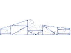
In this next drawing I have eliminated the X-Braces, and left the wheels off since they are not important in this drawing.
The diagonal brace behind the drivers back is just slightly inside of the outter rails of the chassis and secures the rear vertical to the
chassis' floor.
In an ideal situation i would run a bar from the tops of the two verticals, and from the top of the engine area straight forward to the top of the
steering wheel area. But like I said before, how will the driver get in the car?
The last idea I would like to propose is this... Lets say I took the center section thats lowered, and essentially extended that box of support
forward and backwards on the chassis, so basically the bottom of the chassis would be a triangulated box of that height, then any part of the chassis
taller than that would be tacked ontop of that box. would that eliminate some of the weakness?
Here is the new picture...

Rescued attachment Chassis3.jpg
Clay - 20/5/05 at 02:25 PM
quote:
Originally posted by wheelsinsteadofhooves
as for the connections, my main concern would be where the rear section joins the middle point. the diagonal braces meet the transverse members but
there is no support from there on.
there are a few other issues i would raise like the width of the chassis coming all the way out to the edge of the wheels
zane
Zane, in the top view, i made the chassis go out to the edge of the wheels because the body of the car is going to sit on top of the bottom frame. Is
there a reason why I should not do this? Should the chassis width be shortened?
Also, where could I add more support for the rear vertical? I assume the first thing you mentioned was in the top view. The diagonals going from the
center to the rear section do only go to the transverse member somewhere between the transmission and the engine block, but if you look at the side
view, the top members for the rear go from the highest point in the middle of the chassis, all the way to the furthest rear point on the chassis. I
could make the diagonals viewed in the top view extend all the way to the furthest rear point of the chassis also, but then where they attach to the
center section couldnt be attached at the widest point, or the members would interfere with the wheels and such. Would you reccomend making the rear
diagonals viewed in the top view drawing more narrow in relation to eachother so they could be extended all the way to the rear? I thought it was
fairly important that the diagonals viewed in the top view drawing attach to the center at their outer most points.
flak monkey - 20/5/05 at 02:30 PM
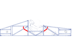
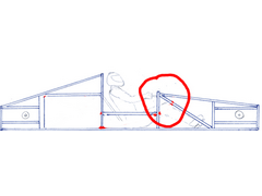
On your last drawing the design is ok, but as you have cut-away cockpit side you have some good bending loads on the cockpit tubes.
A simple and easy to apply rule when it comes to spaceframes is all loads should pass through nodes (there 3 or more) tubes meet.
Hence I would add in some tubes as i have drawn. Follow the angle of the cockpit braces up to meet the others, then bring a tube straight down (or up)
to meet at the node. That modification should bring stiffness up considerably.
Cheers,
David

Rescued attachment chassis.jpg
flak monkey - 20/5/05 at 02:32 PM
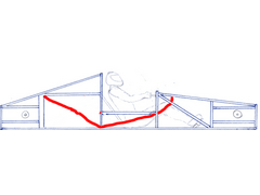
Or you could do away with the V-bracing on the cockpit sides and do something like this, depending on the layout of all your tubes really! Its very
difficult to say what would benefit you with only 2d drawings.
(Sorry about my crappy examples!)
[Edited on 20/5/05 by flak monkey]

Rescued attachment chassis.jpg
ned - 20/5/05 at 02:57 PM
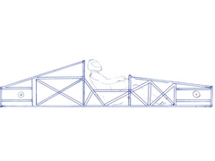
here are my takes on it, narrowing but maintaining the low section for entry to the car. normally on an open top car you step over the side onto teh
seat, then sit yourself down into the footwell.
and the x-bracing can be removed if preferred 

chassis design
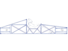

chassis design2
looking at it again, if you wanted you could extend the horizontal member in the middel of hte chassis at either/both ends til they meet with the
x-braces..
[Edited on 20/5/05 by ned]
Clay - 20/5/05 at 04:23 PM
Here is a new idea I tried, the red bar is hinged at the front and swings out with the door, but locks solid when the driver is seated and the door is
closed. Is this a bad idea?
I figure the X-brace in the middle might allow just enough space for the driver to get into and out of the cockpit. It will be akward but similar to a
race car with a serious roll cage i think. This car is designed with a removable hard top, but im trying to design it for getting in and out of the
car if the roof is on.
thoughts on this new revision?
JonBowden - 20/5/05 at 04:25 PM
Ned, this looks like a big improvement.
Clay, You might find it usefull to make a model of your design. Have a look at this thread :
http://www.locostbuilders.co.uk/viewthread.php?tid=21936
Once you have made a model, you can try twisting it to see where the weak points are.
Personaly I would also test a model to destruction to see what hapens inaan accident.
Best wished for building your design
flak monkey - 20/5/05 at 04:31 PM
I have to say I think that neds second one is the best.... 
Clay - 20/5/05 at 04:49 PM
quote:
Originally posted by flak monkey
I have to say I think that neds second one is the best.... 
Will you back that up with some reasons?
Ive been looking at neds 1st chassis as the best one so far because it allows for the driver to lift his leg out and over the side bar to get out.
flak monkey - 20/5/05 at 04:54 PM
I was looking at it as the best technically (probably with some playing about in 3d you could lose some of the cross bracing). If entry and exit
(quickly) are important then you have to make compromises.
The second one is fully triangluated with minimal bending loads on any of the tubes. The top one is missing the triangulation to the top of the
'scuttle'. Though how much difference this makes to the stiffness is anyones guess...
The first one is indeed easier to get in and out of than the second. And if that is important then thats the one to go for.
Also, the one in your drawing doesnt need the cross brace if you change the direction of either the front or rear brace.
David
[Edited on 20/5/05 by flak monkey]
Clay - 20/5/05 at 04:55 PM
Now that I think about it, I think using T-Tops that are hinged in the middle so they open straight up like butterfly wings would allow the passenger
or driver to just lift the top, step in, and close the top over him once hes in. That would get rid of the pesky weak center problem.
And they could just be removed to make the car a convertible.
Lets say we've eliminated the problem about needing clearance for the driver to get in and out of the car, would it be best to just have a setup
like the last one i posted, with the x brace in the middle, and the red bar a solid mounted member?
[Edited on 20/5/05 by Clay]
flak monkey - 20/5/05 at 05:00 PM
If you wish to have a higher top rail then you could do this. Theres no reason for any cross bracing.
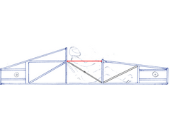

Rescued attachment chasis1.jpg
Clay - 20/5/05 at 05:19 PM
thanks, that makes sense for if the upper brace can be that high.
Clay - 20/5/05 at 06:13 PM
quote:
Originally posted by flak monkey
The top one is missing the triangulation to the top of the 'scuttle'. Though how much difference this makes to the stiffness is anyones
guess...
If the scuttle is the part where the gauges would be directly in front of the driver (sorry im not familiar with this word), this portion of the
chassis is composed of zero force members i believe. So they dont need to be heavily reinforced....to my understanding.
[Edited on 20/5/05 by Clay]
flak monkey - 20/5/05 at 07:03 PM
Think of all chassis members as lines of force. In your original low sided design the area circled is subject to bending forces toward the driver.
These forces would come from the suspension or from cornering etc. By continuing the top rail higher up as in the latest one you have controlled these
forces. Likewise neds design with the double triangulation would work in the same way.
Remember the ideal for a spaceframe is to have all members in compression or tension. But this is not alway practical (in the case of easy entry/exit
for you).
The best way to design a spaceframe is come up wth something close on paper. Get it drawn in CAD and analyse it using FEA. Once that model is good,
then build a prototype and test it on a torsion test rig. Of course ot everyone has access to these things. At the end of the day, any of the designs
you have presented would work, it just comes down to how efficient you want the design to be, and what compromises you are willing to make.
David
PS my 3rd yr uni project is on chassis design next yr 
[Edited on 20/5/05 by flak monkey]

Rescued attachment chassis.jpg
Clay - 20/5/05 at 07:11 PM
I understand what you are saying, but in Ned's first design, the node you selected at the scuttle isnt encountering any forces, in that design,
the node that would be moving towards you, that needs support is the one infront of the scuttle, just in front of the drivers knee.
In the first design, you could completely remove the 2 scuttle members and the chassis rigidity would not change at all. so they dont need support
because its taken care of by the member on front of it. right?
See what im saying?
flak monkey - 20/5/05 at 07:18 PM
Yup, thats right.
Like I say there are many ways to come to the same conclusion, and often, one is no better than another. Neds first design has a lot of
'uneccessary' tubes (needed in that design, but not in others) which come about due to having the low sides on the chassis....swings and
roundabouts.... 
Clay - 20/5/05 at 07:18 PM
what i was saying is that these two structures are equally as rigid, so the scuttle doesnt need to be supported in this design. Am I right?


flak monkey - 20/5/05 at 07:22 PM
Yes 
Clay - 20/5/05 at 07:25 PM
im liking this design for if i have to have lowered sides but im still open to suggestion, this will be my first so help me out with your suggestions
everyone.
kreb - 20/5/05 at 08:09 PM
Well the nice thing about higher sides is more side impact protection. OTOH in a typical locost your elbows would hit the structure, so you'll
have to widen things to have the sill that high.
Clay - 20/5/05 at 09:09 PM
quote:
Originally posted by kreb
Well the nice thing about higher sides is more side impact protection. OTOH in a typical locost your elbows would hit the structure, so you'll
have to widen things to have the sill that high.
This will be considerably wider than a locost, there should be enough room between the seat and the frame for elbow room.
cymtriks - 20/5/05 at 09:50 PM
If you already have a bodshell then it's a good idea to look at the chassis that originally went under it. If you copy that then the body work
wil fit straight on. If you design your own chassis then you will probably need to modify the bodywork.
The GT40 is not too far away in size or concept from the Ultima. Check out the site ultimav12.ca for an excellent set of mods for the Ultima which
result in a decent chassis perfectly adequate for your purposes.
Also try Googling for the Lotus 23 chassis and look at the Lotus 23 busa project thread on the middy section of this forum.
The Lotus 23 and the Ultima both have no tunnel down the car centre, they have sill structures instead. The tunnel on your car isn't adding much,
you may as well delete it.
A word of warning. nearly all kit car space frames are actually less stiff for their weight than simple X braced ladder frames. A ladder of
4x2-14gauge with a scuttle/footwell structure and a triangulated seat back frame would probably be as good as the frames you've discussed so
far.
I've posted some analysis results of spaceframe and ladder frame designs on the locost7.info site under files with the title
kitcaranalysisv2.doc
Good luck with the project!
Clay - 28/5/05 at 06:29 AM
by lookin at a car that is almost identical to what im trying to do, ive noticed how they went about making the frame accessible to the driver.


for me to reduce my upper side rails to 1 low bar like they did, i would have to have a structural back bone and upper rails connecting the 2
verticals in front of and behind the driver correct?
Looking at this chassis as an engineering student, it seems like it would flex, but it seems to be working well enough here in the real world. Perhaps
I should just follow their lead and trust their engineers who certainly have much more experience at this than i do?
JoelP - 28/5/05 at 08:09 AM
damn it i read the entire thread to see if anyone else had suggested that, and there it is in the last post! 

anyways...
the transmission tunnel is a useless waste of space and weight(see edit below). Theres no propshaft to contain, and the strength it adds could be
better added in other ways.
if you need to keep the sides low, just add bars to make a roof. This will make it much stronger and still leave space for a door.
The idea about havign a structural member in the door is pretty hard to do, its never gonna close firmly and solidly without a serious amount of work.
Unless you would bolt the door shut?! 
anyway, that last picture has everything you need for inspiration.
edit:
in the middle picture, you can see how the roof isnt triangulated. In this case it looks more like a roll cage than a fully functional loaded member
of the chassis. Note the remnants of the transmission tunnel, modified due to the absence of the prop, how it aims force straight through one node and
almost directly into the front suspension pickup point (and visa versa).
[Edited on 28/5/05 by JoelP]
britishtrident - 28/5/05 at 09:46 AM
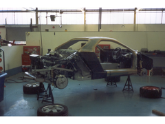
It might be worth looking at the chassis of the the Panther Solo it was based around Sierra bits and I think the design of the rear bay of the
chassis was really clever.
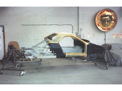

Rescued attachment Mark_Harlow-Solo_chassis.jpg
britishtrident - 28/5/05 at 09:47 AM
more Solo

Rescued attachment Mark_Harlow-Stage_01.jpg
Clay - 28/5/05 at 04:41 PM
british trident, no other pictures of the panther solo?
Also, i dont see how the back bone tunnel doesnt help, if it is a rigid back bone it should help the car from bending at the middle like a V if you
are looking at the car from a side view. It's gotta offer some support.
JoelP - 28/5/05 at 04:49 PM
it does, but not much considering its only 6inches high and wide - the same 4 bars triangulated 40 inches apart would be a lot stronger. its to do
with the distance a part is from the axis of twist or flew, the 'I' value in FEA, i believe.
[Edited on 28/5/05 by JoelP]
Clay - 28/5/05 at 05:00 PM
i figure im going to need every bit of help i can get increasing rigidity at that mid section if im doing to reduce the outer bar to just 1 diagonal
like they did. Maybe the backbone can be improved on to be more supportive. But it looks like i will be working on a roof this week.
britishtrident - 28/5/05 at 06:48 PM
Only 12 Solos were built info is a bit scarce.
On most cars with a backbone the backbone isn't really a main structural member -- even on Lotus road cars it was really just a subframe the
body provided a very large slice of the torsional stiffness.
[Edited on 28/5/05 by britishtrident]
Clay - 28/5/05 at 07:05 PM
it looks like the panther solo has almost no side support members, and little to no visable overhead support.
tks - 28/5/05 at 07:48 PM
i have also some ideas...
building a space frame chasis is also playing the game with space efficienty...
If you see my pic you see the bar going to the top wich on geeting in the car would harm you and i'm pretty sure it will increase the
stiffness
also think you can use some 4mm sheet...
it will not help the forces sidewards....but the flex just up and down will be eliminated if used on the good places with good amounts..
TKS
as you see i have now moved the weakest point more forwards.in the chasis....
anyway this is the typical reason wy a cabrio is more expensive to a normal car one..the desing is much different....
if you can live with the tubes arround your head..it will eliminate allot of tubes on the side...(not mentioning the ones for side impact..)
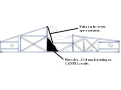

Rescued attachment nedchassis1.jpg
JoelP - 28/5/05 at 07:59 PM
this is my take of it. obviously its only a 2d thing, wouldnt be a direct switch to 3d.
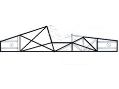

Rescued attachment schmia1.JPG
tks - 28/5/05 at 09:51 PM
it would be the lihgtes option i have seen
but i stil would add one bar..
from the scuttle backwards...
SPACE USEMENT..
Tks
JoelP - 29/5/05 at 09:43 AM
if you could afford the space, that would be much stronger.
ps, if i ever modify this piccy again, i will add the front and back suspension pickup points in, so i can try to like the two together well. big red
dot or something. 
[Edited on 29/5/05 by JoelP]
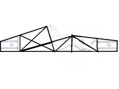

Rescued attachment schmia1.JPG
Liam - 30/5/05 at 11:13 PM
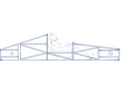
Nice, but I wouldn't like to make it 
Keeping the original shape, wouldn't this be simplest. All triangles...
Liam

Rescued attachment frame.jpg
Liam - 30/5/05 at 11:17 PM
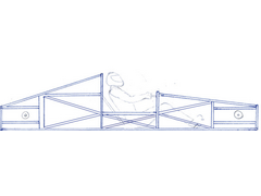
Actually i'd be tempted to cross the sill cos being so low it will be highly stressed...

Rescued attachment frame.jpg
cymtriks - 1/6/05 at 06:23 PM
quote:
Originally posted by me!
If you already have a bodshell then it's a good idea to look at the chassis that originally went under it. If you copy that then the body work
wil fit straight on. If you design your own chassis then you will probably need to modify the bodywork.
The GT40 is not too far away in size or concept from the Ultima. Check out the site ultimav12.ca for an excellent set of mods for the Ultima which
result in a decent chassis perfectly adequate for your purposes.
Also try Googling for the Lotus 23 chassis and look at the Lotus 23 busa project thread on the middy section of this forum.
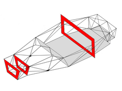
The Lotus 23 and the Ultima both have no tunnel down the car centre, they have sill structures instead. The tunnel on your car isn't adding much,
you may as well delete it.
A word of warning. nearly all kit car space frames are actually less stiff for their weight than simple X braced ladder frames. A ladder of
4x2-14gauge with a scuttle/footwell structure and a triangulated seat back frame would probably be as good as the frames you've discussed so
far.
I've posted some analysis results of spaceframe and ladder frame designs on the locost7.info site under files with the title
kitcaranalysisv2.doc
Good luck with the project!
And take a look at this---

Rescued attachment frame23_pbh.JPG
JoelP - 1/6/05 at 09:31 PM
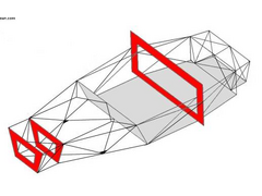
one that can be seen without borrowing NASAs array of monitors

Rescued attachment untitledcy1.jpg


