
"L" section again
Avoneer - 19/3/05 at 12:38 AM
Hi,
Can anyone forsee any problems if I make the top and bottom bar of the "L" in 25mm round?
It enables the whole "L" structure to be made flat, the two upright sections remain parallel to the centre line and you can rotate the whole
"L" section from 3-4" back to suit the suspension setup.
Not bothered about having to make all the fishmouths as they are the exact same diameter as my half round file!
Cheers,
Pat....jpg)
Avoneer - 19/3/05 at 12:40 AM
And when making it, all I have to worry about is the length of the two round bars and that they are parallel with each other - and 13" apart.
The square section can be just made to fit without following the book dimensions for them.
Pat...
dmottaway - 19/3/05 at 02:59 AM
looks like a good idea - certainly simplifies this stumbling point. however, they are more than 13" apart.
looked at from the side, the top surface IS 13 inches above the bottom surface, but the tubes are NOT arranged vertically, there is a
three inch offset.
Again, from the side, draw a horizontal line through the center of the bottom tube, a vertical line through the center of the upper tube, and then
connect the center points. You will have a triangle that is 3 inches across the base, 12 inches tall, and has a hypotenuse (center to center) of
slightly less than 12.4 inches.

So, if the two pieces of wood we see in the pic are 13.4 inches apart, all should be real close.
I hope this is clear, and moreso, I hope my concerns are valid.
dave
[Edited on 19/3/05 by dmottaway]
WIMMERA - 19/3/05 at 06:34 AM
I think you might be onto something here Pat, are you going to make F1, F2 and J1,J2 3/8" longer to allow for the fishmouth that they will need
to connect up. I agree with dmottaway re the length
Wimmera
Jonr - 19/3/05 at 07:51 AM
quote:
Originally posted by dmottaway
.
You will have a triangle that is 3 inches across the base, 12 inches tall, and has a hypotenuse (center to center) of slightly less than 12.4
inches.
I see what you did there!
Ythe hypotenuse is 13.4" center to center but 12.4" inside OD to OD
So the jig should be set to 14.4" wide (outside OD to OD(13.4" + tube radius twice) and cut the RHS to 13.4 ish to allow for the
fishmouths?
square of the hypotenuse (longest side) is equal to the sum of the squares of the 2 shorter sided
[Edited on 19/3/05 by Jonr]
WIMMERA - 19/3/05 at 08:20 AM
I think we may have a problem Pat, when you set it up on the incline the outside face that the brackets attach to is no longer parallel to the centre
line (I think) not a huge problem I suppose just a matter of figuring out how much twist to put into LB LA before you weld it up, you get the same
thing on a normal L frame, the LB LA have to be twisted a shade to square them up to the centre line.
Hoping I'm wrong
Wimmera
907 - 19/3/05 at 08:27 AM
Hi All,
I have just looked at this in the "book"
and am amazed with Ron's obsession with
wood for jigs.
Surely, an offset of 75mm is just 3 offcuts
of box, on top of each other. You'll have
loads of the stuff laying about, ( or in your
scrap bin if you are a tidy chap. I'm not. )
It's hard to find a bit of wood 75 / 76mm
thick anyway. It will be 3" planed, which is
about 70mm.
Anyway, back to the subject.
Don't forget that the ends of J1, J2, F1 &
F2 will become half fish mouth, half square
and the ends of S & T will need fish
mouths as well.
I hate to harp on about it, but these parts
are so easy to cut with a band saw, in box
section that is.
Paul G
Avoneer - 19/3/05 at 08:51 AM
Hi Guys,
I though the 13" was the height when the whole "L" section is already leaned over?
No problem making it lightly taller though.
Yep, I know I'll have to fish mouth the "J"'s and the "F"'s and a few others, but I have an obsessin with round bar
and don't mind doing it!
The uprights should remain dead parallel as they are only rotating on the axis of the bottom round.
No one has forseen any major problems though....yet....
Cheers,
Pat...
Avoneer - 19/3/05 at 08:57 AM
P.S. It wasn't my original idea.
It was briefly mentioned in this post by niceperson709.
http://www.locostbuilders.co.uk/viewthread.php?tid=23639#
Pat...
Avoneer - 19/3/05 at 09:12 AM
Thinking abour this 13" - it will always be 13" whatever angle it is at won't it????
As I am going to mount the top round 4" behind the bottom (due to the wishbone bracket scenario) all I'll have to do is make sure that the
top round bar is the same height as the top of the chassis bars when it's leant back 4"????
Pat...
[Edited on 19/3/05 by Avoneer]
WIMMERA - 19/3/05 at 09:14 AM
Yes it is only rotating around the bottom tube, but the bracket lies horizontal viewed from the side thats where the problem may be, it's
attached to sloping plane.
Wimmera
Avoneer - 19/3/05 at 10:08 AM
Sorry, yes, I can see the wood through the trees now - just me being thick.
Pat...
Jonr - 19/3/05 at 10:18 AM
the 13" will always be the same as this is the height of the chassis, though if you push the angle back a bit then the lengths of LA, LB are
going to change.
So if your going for 4" of difference in length between he top and bottom of the chassis that changes the length of the hypotenuse.
so
square of the hypotenuse = sum of the square of the 2 shorter sides
so
13" squared =169 - chassis height (height of the triangle)
+
4" Squared = 16 - difference in length between top and bottom rails (Base of the triangle)
4"
= 185
square root of 185= 13.6"
that's center to center so you will have to add an inch of the tubing (2 half inches, 2 x radius)
Avoneer - 19/3/05 at 11:57 AM
So that would be an extra inch on each of the two square uprights ones (if I use a 4" recline)?
Cheers,
Pat...
clbarclay - 19/3/05 at 02:05 PM
I agree with WIMMERA. making tubes LC/LD out of round still leaves you with the problem of getting the suspension braket mounting points parallel with
the centre line, just like using square for the all the L tubes.
dmottaway - 19/3/05 at 05:01 PM
how about going at it from a different angle, such as making the LA/LB tubes round and the LC/LD tubes square?
then just have to notch the ends of the horizontal members and give no regard to rotating the LA/LB tubes.
suspension brackets could be welded on in the proper orientation then gusseted for strength.
britishtrident - 19/3/05 at 06:32 PM
There is a quick and nasty way to avoid having to make fishmouths I saw it used on some some ships plant. I haven't tried it myself.
Chop a short length of 25x25x2 to form a channel section about 8mm deep and use it as a sort of quasi fishmouth welded on to the end of the tube how
good it is will depened an awful lot on the welders skill.
in ASC11 symbls it would be something like this
o]====
[Edited on 19/3/05 by britishtrident]
WIMMERA - 20/3/05 at 04:04 AM
Glad I'm 12000 miles away from that one B/S
Wimmera
Avoneer - 20/3/05 at 09:11 AM
Anyway,
I've done it with round top and bottom and a 4" recline.
I'll post pics later and keep you all infromed, but it looks good so far and looks a lot tidier than using box section.
Pat...
Peteff - 20/3/05 at 10:08 AM
I made mine in square with a 4" lean instead of the 3" in the book. I made the chassis 1" taller as well. It will put your fu tubes
further back as well and may affect where your damper bracket goes on your bottom wishbone but I haven't got to that bit yet.
Avoneer - 20/3/05 at 05:53 PM
Right, update:
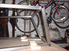

Rescued attachment 1.JPG
Avoneer - 20/3/05 at 05:54 PM
And this:
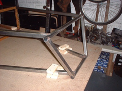

Rescued attachment 2.jpg
britishtrident - 20/3/05 at 06:41 PM
That will do nicely :-)
Avoneer - 20/3/05 at 08:07 PM
We'll just have to see what happens when I try to fit the bones!!!!
Must admit, I think it looks a lot better than using square tube for the top and bottom bars.
Pat...
WIMMERA - 20/3/05 at 09:01 PM
Looks good Pat, a good test would be to clamp a piece of tube say 2 foot long to the side of the L tube to sort of replicate a bracket and check if
it's parallel to the centre line, better to know now than after it's fully welded.
Wimmera
niceperson709 - 21/3/05 at 06:04 AM
Ah it is good to see my idea in the metal and I think it looks really good , the essense of good design is simplicity and elegance . Good work Mr
Avoneer !!!! 
Best wishes
Iain
Mix - 21/3/05 at 07:26 AM
I'm a bit late to comment but Wimmera has been right all along IMO.
As constructed the pivot axis of the brackets if they are welded directly to the LA LB tubes will converge towards the front 
Not an insurmountable problem just make sure you use a jig to ensure that the pairs of brackets end up parallel to the chassis centre line.
Don't be tempted to clamp and weld flush to the L tubes.
Mick
niceperson709 - 21/3/05 at 07:40 AM
"I'm a bit late to comment but Wimmera has been right all along IMO.
As constructed the pivot axis of the brackets if they are welded directly to the LA LB tubes will converge towards the front "
sorry mate but you are totally wrong !the sides of the assembly will be parralell to the center line of the carif they have been made flat in the same
way that the ones in the book are parralell to the centerline . The whole point of the exercise is to make construction easier with out altering the
fundementals of alignment . I think that both you confusing the inclination of the whole assembly with a change of the anglarity of the La /Lb tubes
.
best wishes
Iain


Mix - 21/3/05 at 07:57 AM
I think you'll find that if you think about it the sides will indeed be parallel to the centre line when the L assembly is perpendicular to the
base line. However as you tilt the L assembly to the rear but keep the wishbone brackets parallel to the base line their pivot axis converges to the
front.
Imagine the extreme case of laying the L assembly flat, a bracket with it's pivot axis parallel to the base line would also have the pivot axis
parallel to the LA / LB tube.
I rest my case.... I think 
Mick
WIMMERA - 21/3/05 at 10:30 AM
Suggest you have a think about that Iain, easy enough to prove visually with a couple of match box's and a right angle set square.
Wimmera
Peteff - 21/3/05 at 11:12 AM
Time for a fat weld I think  .
.
Avoneer - 21/3/05 at 12:45 PM
Right, for whatever reason, the square sections are ever so not quite parallel at the top (too hard to visualise the physics).
Not that bad though as the top front bone brackets will only have to be angled by about 1mm at the front to remain parallel.
Will be attempting to fit the brackets next week so will let you all know what happens.
As for makind the "L" section - boy it was so bloody easy.
Pat...
[Edited on 21/3/05 by Avoneer]
Mix - 21/3/05 at 12:50 PM
Just to try and clarify.
All of the brackets mounted on the L tubes will have to be angled out slightly at the front.
As Pete says, 'time for a fat weld'
As long as you are aware of the situation you will easily overcome it.
Mick
Avoneer - 26/3/05 at 06:30 PM
Right - update time.
Yes, the front brackets are all slightly angled, but only by around 1 - 1.5mm.
Fat weld time as suggested?
Isn't too difficult to rotate the uprights a little bit though, but may be more hassle than it's worth.
As for the camber in relation to my 4" recline - it looks good will all the brackets in the centre of the uprights. FU1 and FU2 to cut and fit
yet, but I can do them to suit.
The top ball joint centre is approximately 50 mm towards the rear of the car in relation to the bottom one. Does this sound about right, as the top
bone can be moved about another 10mm back if necessary.
Cheers,
Pat...
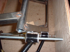

Rescued attachment Gap.JPG
Avoneer - 26/3/05 at 06:30 PM
Ariel pic:
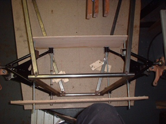

Rescued attachment ArielPic.JPG
Avoneer - 26/3/05 at 06:30 PM
Side view:

Rescued attachment SideView.JPG
niceperson709 - 26/3/05 at 08:53 PM
Looking good pat from the photos it looks as if your side pieces would be best with a little tweeking while it is still just tacked better now than
when fully welded .
Best wishes
Iain
WIMMERA - 27/3/05 at 06:50 AM
50mm is more than twice what you need for 5.5 degrees of castor, as far as filling the gap between the bracket and L tube, what have you got against
doing the job properly ?
Wimmera
Mix - 27/3/05 at 08:39 AM
50mm balljoint displacement equates to 13.1 degrees of castor 

Mick
Guess we were correct then Niceperson 

Mick
[Edited on 27/3/05 by Mix]
[Edited on 27/3/05 by Mix]
Peteff - 27/3/05 at 09:40 AM
Have you measured that Pat? it doesn't look that drastic. I did mine with 4" lean on it and it came out nearer what it should be. I made my
wishbones so the top outers lined up with the bottom inners and used steel strips instead of wood to line stuff up.

Rescued attachment SideView.JPG
Avoneer - 27/3/05 at 10:23 AM
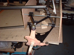
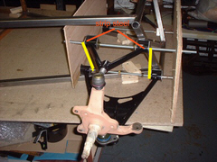
Right, with the inner edge of the lower bracket in line vertically with the front edge of the upper bracket, the top ball joint is approximately 6mm
behind the bottom one - this should just about be right shouldn't it?
And if it is right, both brackets fall right in the centre of LA and LB.
Pat....JPG)
Mix - 27/3/05 at 11:12 AM
Assuming your ball joint centre to centre distance is about 220mm you will require an offset rearwards of 22mm to give a castor angle of 5.6
degrees
Mick
6mm will only give 1.54 degrees castor
[Edited on 27/3/05 by Mix]
Avoneer - 27/3/05 at 11:58 AM
But if I move it back so it is 20mm behind the bottom ball joint, the edges of the brackets don't line up anymore and the front upper wishbone
bracket is hanging off the front upright - strange when the upright is 4" further back at the top.
I'm all foncused now!
Pat...
WIMMERA - 27/3/05 at 12:49 PM
If the top bones are the same as the book they have 3/8" offset, are they on the right way or arse about, you might have to move the bottom
bracket forward, it's not necessary for the edges of brackets to line up
Wimmera
Mix - 27/3/05 at 01:58 PM
Pat
I suggest you lock your threaded rods to your jig with locknuts.
Then position and lock the brackets the same way so as to achieve the correct offset.
Finally offer up to the chassis and position for the best fit.
Wimmera's point re the symetry of the top bone is correct, have you got it fitted in the correct orientation??
Mick
MikeRJ - 27/3/05 at 05:37 PM
quote:
Originally posted by Avoneer
But if I move it back so it is 20mm behind the bottom ball joint, the edges of the brackets don't line up anymore and the front upper wishbone
bracket is hanging off the front upright - strange when the upright is 4" further back at the top.
I'm all foncused now!
Pat...
Unfortunately this is down to the incorrect measurements in the book. The required 22mm does indeed move the brackets enough that they are
"hanging off". The ideal solution is to redesign the front wishbones to correct this, but given that you already have servicable wishbones
you may not want to do this. Alternatively you could add an extra tube in to support the brackets as I have:

Avoneer - 27/3/05 at 05:59 PM
Will re-check everything and hopefully with the 4" lean, that should cover the hanging off the bracket scenario.
Will update when I get some more gas.
Pat...
.jpg)


