MSA-Roll protection compliance
liam.mccaffrey - 5/8/15 at 01:37 PM
I'm building a middy along the lines of Midlana, I intend to make my roll over protection/cage to comply with the bluebook specs in order to hill
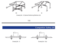
climb. I've been looking at section K and have a question about how deal with the footplate detail shown at the roll bar to chassis
connections.
My intention was to incorporate the cage as part of the chassis not as an add-on. Which would mean the footplates would not be required. My question
is whether my cage would be compliant if it was fully incorporated into the chassis, without the footplate but other wise as per bluebook.
Anyone know
[img]


ksnip
[/img]
[Edited on 5/8/15 by liam.mccaffrey]
Badger_McLetcher - 5/8/15 at 04:27 PM
Not sure about MSA compliance, but you'll still need a load spreader I'd imagine, so just one plate with the roll cage welded onto it rather
than the two shown.
[Edited on 5/8/15 by Badger_McLetcher]
DIY Si - 5/8/15 at 09:29 PM
I think that if you made the cage part a different size/thickness of tube to the rest of the passenger bay, then it would need something to link it
back into the chassis. However, if there was a roll cage tube pod that you sat in the middle of, I can't see the need for any load spreaders as
all the tubes would be the same size, and just happen to be classed as a cage.
Regardless of what any of us think on here, you might be best off getting yourself to a hill climb meeting and asking the scrutineers, as it's
their opinion/interpretation of the rules that matters.
liam.mccaffrey - 6/8/15 at 06:18 AM
Another forum member has put me in touch with a local scrutineer/competitor who has kindly agreed to help I'll let you all know how it goes 
dai1983 - 12/8/16 at 11:06 PM
Any news on how you got on with this? It's a question I've been pondering myself.
jeffw - 13/8/16 at 05:51 AM
Speak to the MSA Technical Department. technical@msauk.org
tymkea - 13/9/16 at 01:30 PM
I am years out of touch.
The methods available were to use accredited manufacturers, or to design to the loads specified in the blue book.
The loadings were quite onerous and need some method of calculating the forces and moments generated in the various members.
In 1988 I used a 3D space frame calculator that operated in DOS before Windows came to the scene.
I used that same calculator to establish all the member loads for a variety of suspension loads including hitting a gentle kerb and such like.
The calculator also allowed me to determine an approximation of torsional stiffness of the spacefram.
[Edited on 13/9/16 by tymkea]
[Edited on 13/9/16 by tymkea]
[Edited on 13/9/16 by tymkea]


