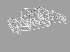

Rescued attachment chassis1.jpg

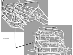
Hi all, just found this web site to day while try to do so research while I was meant to be working, I am mad about all things cars like most of you
seem to be here so I guess I am in the right place, I am in the process off finishing a vtec powered mini and have caught the car building bug big
time and want to take a leap in to the deep end and build my own design of car from scratch, I am a computer engineer by trade but cars are my first
love, I download rhino’s 3d/cam demo and off ive gone, I am just looking for constructive criticism to what you think of my first attempt at
designing my first very own chassis its a mid mount layout design drawn to 1/10 scale to house a Chevy small block mated to a porche g50 box, please
feel free to comment.


Rescued attachment chassis1.jpg
Looking v. nice  certainly using heavy tubing by the looks of it! What size is it?
IMHO could probably do with more triangulation down the sides, just a singe brace across each 4 sided area  will make the chassis much stiffer.
People may disagree though....
[Edited on 23/2/04 by flak monkey]
Like so should that be better

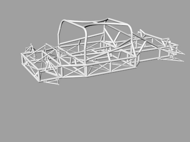
Rescued attachment chassisextra.jpg
The tubing i want to use would be 38mm by 1.5 mm thats what ultima uses so its good enought for me its lookings bigger on the drawing because i slipped up, on the pic the tube is 2 inches oops
Very nice, weight is not the most important thing the strenght of the chassis to me will me, with the chevy setup i want to run with be pumping out 450 ft/lbs and bhp the chassis needs to be tought, was ive read that round tubes are much stronger to size and wieght compared to tubing thats what ive gone for, reguarding cutting the tudes to mate up with the other sections i all ready have a fish mouth cutting tool for the job
Ok there are a probably a few more bits i have missed and i have only done one side, but this is the general jist of what i mean  . Feel free to tell
me to pi55 off though and ignore me
Good luck with your dream machine!
Cheers
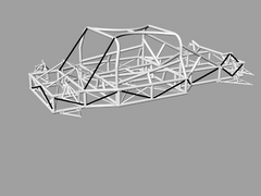

Rescued attachment like this.jpg
i was gonna point out the rear suspension pickups! Plus, the engine bay could use some horizontal traingulation, though i appreciate this is nearly
impossible without having the drivetrain to work around.
consider welded panels on the sides, i suspect it would compare favourably with braces for stiffening.
nice try, doesnt look like a first attempt though! was it computer engineer or mechanical engineer you said?!
Heres some more improvements i cant have the long down bars running down from the top of the frame because on the layout of the body work
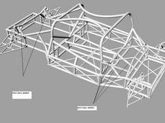

Rescued attachment back supen.jpg
You should read the chassis notes by a member of this forum called cymtriks there's a link to his analysis here - www.locost7.com look in the FEA
section. This guy's work has a ring of authority about it.
triangles are the key to spaceframes. I think the round vs square tube thing is overblown - round tubes are intrinsically stronger in torsion (but
this does NOT equate to significant extra torsional stiffness in a spaceframe) square tubes make stronger beams & are easier to rivet sheets to
and easier to joint - so most folk use square. They're the same in compression/tension which is how they're loaded in a spaceframe.
BIG job you've given yourself there; years of fun!
Bob C
Thanks alot for all the help its much appreciated theres probably going to me many more questions to come.
i take it the front is the end with the a-arm suspension? if so, the cockpit looks a tad long, the window suround seems to be directly above the font
bulk head where the pedals would appear to be going. it either is very weird or i dont understand the layout fully. also, you seem to have a lot of
tubes ending in the middle of other tubes where you could quite easily group them together into the same joint. round tube has a better strength in
compression and tension but is significantly weaker in bending than square tube so this ought to be avoided.
and triangualtion is the way to happiness!
I no im a pain but with a bit on reworking i thinks im going down the right lines now (i think) :-0

Rescued attachment reartrifount.jpg
Its looking very good but very complex! 
I disagree with Suparuss though about round and square tubes. If anything round tube is WEAKER in compression and tension than the equivalent sized
square tube.
Say comparing 50mm RHS (2mm thick) and 50mm tube (2mm thick). The square tube has more cross sectional area (add it up if you dont believe me - thats
why it is heavier per unit length) so;
extension = (Force x length)/(cross sectional area x youngs modulus)
(Youngs modulus is constant  ) So with the same force the square tube will deform less than the round tube.
Round is better in torsion, but there is little of this in a space fram chassis. But square resists compression/tension better 
Square wins for me 
Lecture over...can all tell me where to go now 
Cheers
[Edited on 23/2/04 by flak monkey]
[Edited on 23/2/04 by flak monkey]
[Edited on 24/2/04 by flak monkey]
quote:
Originally posted by flak monkey
....... If anything round tube is WEAKER in compression and tension than the equivalent sized square tube........
quote:
round is better in torsion, but there is little of this in a space fram chassis. But square resists twisting better
Sorry was a typo :-S and still with 2 edits i didnt spot it... sorry
Cheers
Taking the discussion a stage further,
If you were to consider the merits of round and square section material of similar cross sectional area, (ie in the previous example if the gauge of
the round section was increased or it's diameter increased) and therfore equal weight per unit length, what would be the outcome?
At least this way we would be comparing like with like.
Mick
This all comes down to second moments of area, the bending moment in the 'beam' (tube) and the stress in the tube.
The second moment of area of RHS assuming it is square is;
Ia = [(length of 1 side in m ^4)/12] - [(internal measurement in m^4)/12]
For a piece of 25mm RHS with wall thickness of 1.6mm this would be = 1.373x10^-8m^4 [The cross sectional area would be - 0.00015m^2]
A round tube with similar cross section would be 25mm with a wall thickness of 2.08mm.
The secomd moment of area of a peice of tube is;
(pi/4) x (O.D^4 - I.D^4)
For the round tube described above Ia = 1.59x10^-7m^4
The general beam equation is;
(Bending moment/Ia) = (stress at distance y from neutral axis/distance from the neutral axis)
And i bet that doesnt make any sense what so ever! 
Cheers
Edit: both tubes will now behave the same in compression, but will still act differently in bending/torsion
Edit 2!!: Right checked, HIGHER second moment of area means MORE resistance to bending (look at I girders). So ROUND TUBE IS BETTER FOR YOUR
CHASSIS, it resists bending more than square tube. Sorry for the confusion!!! I will shut up now
[Edited on 24/2/04 by flak monkey]
[Edited on 24/2/04 by flak monkey]
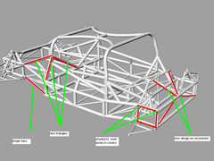
Here are some more modifcation do to my chassis as recomened. thanks agian for all the help.

Rescued attachment chassis24th.jpg
looking good ---- but
you seem to have lost a bit of the triangulation that was present on earlier models
specifically i notice that the front suspension 'box' only has one face braced. I would have thought that this was an area where stiffness
was essential so this should be fully braced in all planes...
Flak Monkey and others,
Comparing sizes and tube/RHS is all very good, but can we keep it relevant.
Gazr81 has said he is planning on using 38mm (1 1/2 inch) by 1.5mm tube.
If you have to do comparisons then try to use the sizes that are being planned. This makes it easier to use and work out the problems.
If there are no equivalent square/round tube then the comparison is pointless.
It annoys me no end when people start comparing material strengths that are not relevant to the thread!
(Rant over) 
Terry


[Edited on 24/2/04 by Spyderman]
Sorry, was using the tube sizes as guide lines to clarify a point. And they make my calculations easier!
The same points will apply to whatever sized tubing is used.
If the cross sectional area is the same, then square resists bending better than round.
If the wall thicknesses are the same then square resists compression/tension better than round.
In all cases round is better in torsion than square!
Thank you for your comments spyderman, but like i say i was only giving examples.
David 
quote:
Originally posted by Spyderman
........It annoys me no end when people start comparing material strengths that are not relevant to the thread!
(Rant over)
Terry


Flak Monkey
Thanks for taking the time to try to educate me 

Must admit I understood your last post a lot easier.
Spyderman
Sorry if I caused you stress but I thought that the whole point of this forum was the free exchange of information amongst like minded individuals.
Discussions will always diversify with time, where should we draw the line ?
Mick
Not a problem mate, gave me something to take my mind off the stupid amount of work i have to do!
I hope they clarify some points without being too specific or irrelevant.
Cheers
David
quote:
Originally posted by Mix
Spyderman
Sorry if I caused you stress but I thought that the whole point of this forum was the free exchange of information amongst like minded individuals. Discussions will always diversify with time, where should we draw the line ?
Mick


according to this book by forbes aird, square tube has a theoretical buckiing load of about 17% less than round in compression. (in tension, shape
doesnt matter only the amount of material.
it contradicts those calculations that i didnt understand but it makes sense. backed up by the fact that (as far as i know) every race car that uses
tube, uses round tube instead of square, even though its harder to cut (fishmouthing).
correct me if i am wrong as always! 
[Edited on 24/2/04 by suparuss]
No i am probably wrong! 
Wouldnt be the first time. Its maths we have just covered in my uni course, that i dont fully understand, but thought that was right.
I have edited my post so it is now correct! Was a misunderstanding of the pricipals that we have just covered in maths :-S. Apologies all
'round'
Cheers
David
[Edited on 24/2/04 by flak monkey]
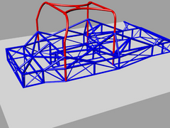
Hi all thanks for all the comments ive reworked the whole chassis with a use-able bulkhead and alot more trianglated sections any more constructive
criticism would be a help

Rescued attachment 26threworked1.jpg
looks very complicated!
there is however a huge gap in your triangulation, im notsure where the wishbones mount so it may be behind that and not important but it is directly
below what appears to be the upper mounts for the shock absorbers, the trianulation ends forewards of it, and then there is a bit on top, but the
whole rear (wishbone and shock mounts, and possible gearbox mounts if they are far enough back) is held on by four straight tubes. 
saying it looks complicated, id be inclined to rethink and try and make the whole thing more efficient, then again i noticed someone else mentioning
the "birdcage" in the other thread, ive seee nthis in a book and its got more tubes than yours so its been done before.