Matching Fuel Sensor, tank shape and Fuel Gauge
theprisioner - 28/7/12 at 03:20 PM
I have a very odd shaped tank in my Sylva build. This has resulted in two issues:
1) Matching the sensor (VDO) to a gauge of my choice.
2) Very non linear gauge calibration.
I decided to see if there was a reasonably simple technical solution without costing mega bucks.
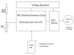
The following design was implemented using a very simple 8bit computer called a PIC. One 8 pin chip does most of the work and a Spread Sheet on the
computer does the rest.


Description


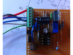
Breadboard Fuel Gauge
In principle any Fuel Sensor/Tank Shape/Fuel Gauge can be catered for. All you need is some basic math skills of curve fitting and the ability to
solder 18 parts together.
I managed to map my setup with a couple of days work.
I am not proposing to do the work for you but I am willing to share more details if you have a similar problem.
Questions welcome?
Macbeast - 28/7/12 at 07:30 PM
Sounds just what I need. Will it match where the meter reads in reverse, ie meter shows empty when tank is full and vice versa ?
theprisioner - 28/7/12 at 07:34 PM
Yes but
This comapny appears to do this also:
https://www.spiyda.com/magento/index.php/vehicle-electronics/fuel-gauge-electronics.html
However their product will not cope with non linear shapes in terms of the fuel gauge reading. That is why I ventured along my route.
My electronics also has a low fuel warning LED designed in.
Macbeast - 29/7/12 at 07:06 AM
Good link - thanks.
I'm not worried about linearity - just full, half and get your wallet out will do 
big-vee-twin - 29/7/12 at 08:29 AM
I've got a wizard from Spiyda, they work quite well, but take ages to set up.
theprisioner - 29/7/12 at 10:26 AM


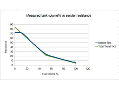
Fuel tank non linearity
I had to fill the tank at 1/2L intervals from 0L to 25.5L noteing the resistance of the VDO sensor each time. Input the data into a spread sheet,
curve fit the tank response (Trend 1+2), and then imbed the resulting table into the PIC source code. Fortunately someone else wrote most of the
Assembler source. Then take the Maplin programmer and flashed the PIC.
And not to forget the component sourcing build time for the hardware.
coozer - 29/7/12 at 11:50 AM
Does this allow the OEM Fiesta tank sender to work with any gauge?
theprisioner - 29/7/12 at 02:16 PM
The older tank sensors are two wire the sensor acts like a variable resistor. In the case of a three wire jobby it acts like a potential divider (POT
- like the volume control on your grandfathers telly).
I would have thought the Spiyda product would work with the Fiesta OEM tank sender unless there is something very peculiar about it. The general
solution would be just to use two of the wires.
The only thing I know about the Fiesta sender is it is three wire. I have a puma sensor so I will measure that and post you a PM reply.
My cct with some investigation would work no problem. You could help here by measuring the sender device wth an ohm meter from Maplin. I can tell you
how if you are stll curious! That information may allow you to use the standard Spiyda product.
In my cct the only difference it would make is a specific choice of current source resistor and possibly not even that. I would of course require you
to charicterise your tank sender combination so we can program the computer. It would be more work going my way.
chillis - 30/7/12 at 11:56 AM
Ohh yes very interested in this, I have a VDO gauge and a Metro sender that seem to be in no way compatable.
What bits do I need and where to get them from.
theprisioner - 30/7/12 at 04:52 PM
1) What is the resistance range of my Sender
(if you are not sure use an Digital Multimeter from Maplin or the like and measure it out of the car)
2) Does the resistance range increase or decrease towards FULL.
3) Obtain the desired resistance range for your Gauge, look up the spec or measure it.
To measure it, buy a 200 ohm 1W pot from Maplin or RS Components connect it in place of your tank sensor (Wiper and one end of the POT only usually).
Note where the full and empty resistance falls on the potentiameter range. You will need a cheap digital multimeter also available from Maplin or the
like.
This gives you desired resistance and direction towards Full.
4) Go to the:
https://www.spiyda.com/magento/index.php/vehicle-electronics/fuel-gauge-electronics.html
and look up their table of compatibility. It list all the common sender ranges and meter ranges/types.
If the list does not cover your application then I will give you all the details you need to build my circuit.
All of the applications discussed on this forum so far are covered by the spiyda product except mine.
It looks like my circuit is a solution still looking for more than one application.
theprisioner - 31/7/12 at 03:51 PM
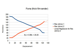
Thanks to coozer's comments it motivated me to look at the puma fuel sender as it might be similar to the fiesta. It is a peculiar animal but not
that much. It is a Potentiometer with the wiper grounded to earth. It is in fact linear so will work with the spiyda product or similar I guess. If
you use one of the sender wires either the 140 -20 ohm decreasing with fuel level or the 60-180 ohm increasing with fuel level. Unless the Fiesta is
different of course, I would have to measue that. Does anybody have a Fiesta sender going spare?


Puma Fuel sender
monkeyarms - 1/8/12 at 06:40 AM
I can confirm that the Fuel Gauge Wizzard does work with a MK4 Fiesta sender unit - thats what I have, connected to a ETB Gauge.
Works well, takes a bit of setting up but is very easy.


